Signal selection systems

a signal selection and signal technology, applied in the field of improved antenna techniques, can solve the problems of severe co-channel interference, co-channel interference, and communications systems can still suffer from the effects of multipath fading, and achieve the effects of reducing complexity, facilitating high data throughput, and alleviating the influence of severe multipath and/or co-channel interferen

Active Publication Date: 2008-09-16
KK TOSHIBA
View PDF12 Cites 42 Cited by
  • Summary
  • Abstract
  • Description
  • Claims
  • Application Information

AI Technical Summary

Benefits of technology

The present invention relates to an improved antenna system that can reduce complexities associated with previous methods while addressing issues such as multi-path interference and co-channel interference. It achieves this by working in the pre-OFDM or time domain, leading to higher data throughput and greater communication system capacity. Additionally, it reduces power consumption and simplifies the overall design of the receiving equipment, making it more efficient than existing solutions. Overall, embodiments of the invention enable faster processing times and better performance in challenging environments.

Problems solved by technology

The technical problem addressed in this patent text relates to finding improved ways to detect and address the challenges faced when transmitting over multiple paths inOFDM communication networks, including issues related to multi-path fading and co-channel interference. Various solutions have been developed, but they come with their own limitations and trade-offs between simplicity and efficiency. There is a need for simpler yet effective methods that can effectively mitigate the impact of co-channel interference while maintaining efficient network operation.

Method used


Image

  • Signal selection systems
  • Signal selection systems
  • Signal selection systems

Examples


Embodiment Construction

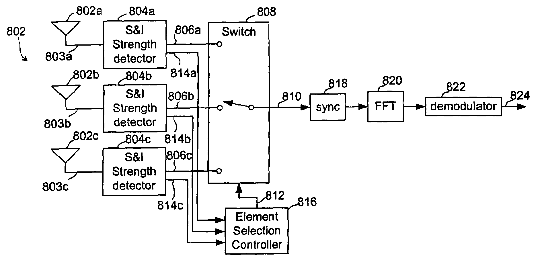
[0052]Referring to FIG. 8, this shows a schematic diagram of a received signal selector 800 according to an embodiment of the present invention. A sectorised or array antenna 802 comprises a plurality of antenna elements 802a, b, c each coupled to a respective input 803a, b, c of a signal and interference strength detector 804a, b, c. Other conventional components such as downconverters and filters may be present between the antenna elements and the signal and interference strength detectors but, for simplicity, these arc not shown. Each signal and interference strength detector has a first output 806a, b, c comprising a straight through version of the input signal, optionally buffered or amplified. These first output signals are provided to a switch or selector 808 which selectively provides one (or in other embodiments, more than one) of these signals to an output 810 (or to a set of outputs 810) in response to a control signal 812.

[0053]Each signal and interference strength detec...


PUM


Abstract

A received signal selector for a received signal, the received signal including a set of carriers, the received signal selector being configured for use with an antenna system including a plurality of antenna elements. The received signal selector includes a plurality of received signal inputs for receiving signals from the plurality of antenna elements, an interference detector for each of the received signals inputs, coupled to the received signal inputs to receive, from each input, a version of the received signal, and configured to provide an interference output for the set of carriers from each input, a selection controller configured to receive the interference output for each input and having a control output, and a selector coupled to the received signal inputs and responsive to the control output to select one or more of the versions of the received signal for output. The invention provides a simplified technique for mitigating the effects of co-channel interference and severe multipath distortion.

Description


Claims


Application Information

Patent Timeline
Owner KK TOSHIBA
Why Eureka
Try Eureka