
Anti-clogging showerhead device

a showerhead and anti-clogging technology, applied in the field of showerheads, can solve the problems of showerhead clogging, clogging of spray holes, and slow accumulation of mineral deposits or scale inside the showerhead,

Inactive Publication Date: 2008-09-23
FRAZEE JOHN S
View PDF25 Cites 9 Cited by
  • Summary
  • Abstract
  • Description
  • Claims
  • Application Information

AI Technical Summary

Benefits of technology

The device ensures complete drainage and prevents mineral deposits, eliminating the need for frequent replacements and harsh chemical treatments, while being environmentally friendly and cost-effective.

Problems solved by technology

Mineral deposits or scale slowly builds up inside the showerhead and on its outer / lower surface and eventually clogs the spray holes.
Hard water is the principal cause of showerhead clogging.
Deposits within the showerhead distort and weaken the shower spray destroying the enjoyment and / or effectiveness of showering.
Besides rendering them less than effective, they buildup of deposits are unwelcome in most environments since they are unsightly and suggest an unclean condition.
Mechanical descaling or chemical removal is not a welcome solution, since the former can be damaging to fine chrome or brass finishes and the latter requires strong acids for dissolution, a procedure posing an unhealthy situation for the laborer and may damage the surrounding trim.
Moreover, the chemical residue from the chemical procedure is incompatible with preferred environmental standards.
Another method of treating lime scale is soaking the showerhead in vinegar, but this is generally found to be somewhat labor intensive and ineffective.
This is especially true when considering the additive costs of new equipment purchase, labor and associated expenses involved in the effort.
Substantial elimination the root cause of the scaling obviates harsh chemical treatment of the clogged facilities.
To date, none among prior art documentation has offered the effective and elegantly simple solution presented herein.
This type of valve, of course, would not be applicable in a showerhead setting where discharge is into an open atmospheric environment and backflow is not an issue.
Moreover, inserting the valve structure presented by Burke into a shower system would not cure the problem of mineral deposits since Burke includes slits defining flaps which will, upon flow shutdown, retain fluid within the rubber element.
Hence, there is nothing (in the way of mineral deposits) to treat or remove.

Method used


Image

  • Anti-clogging showerhead device
  • Anti-clogging showerhead device
  • Anti-clogging showerhead device

Examples


Embodiment Construction

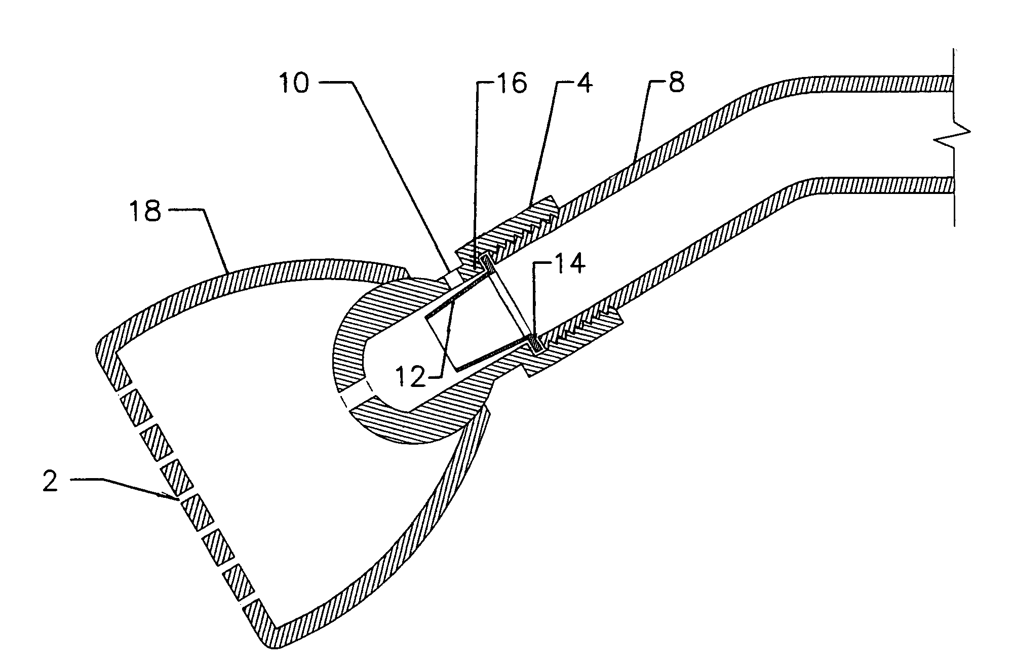
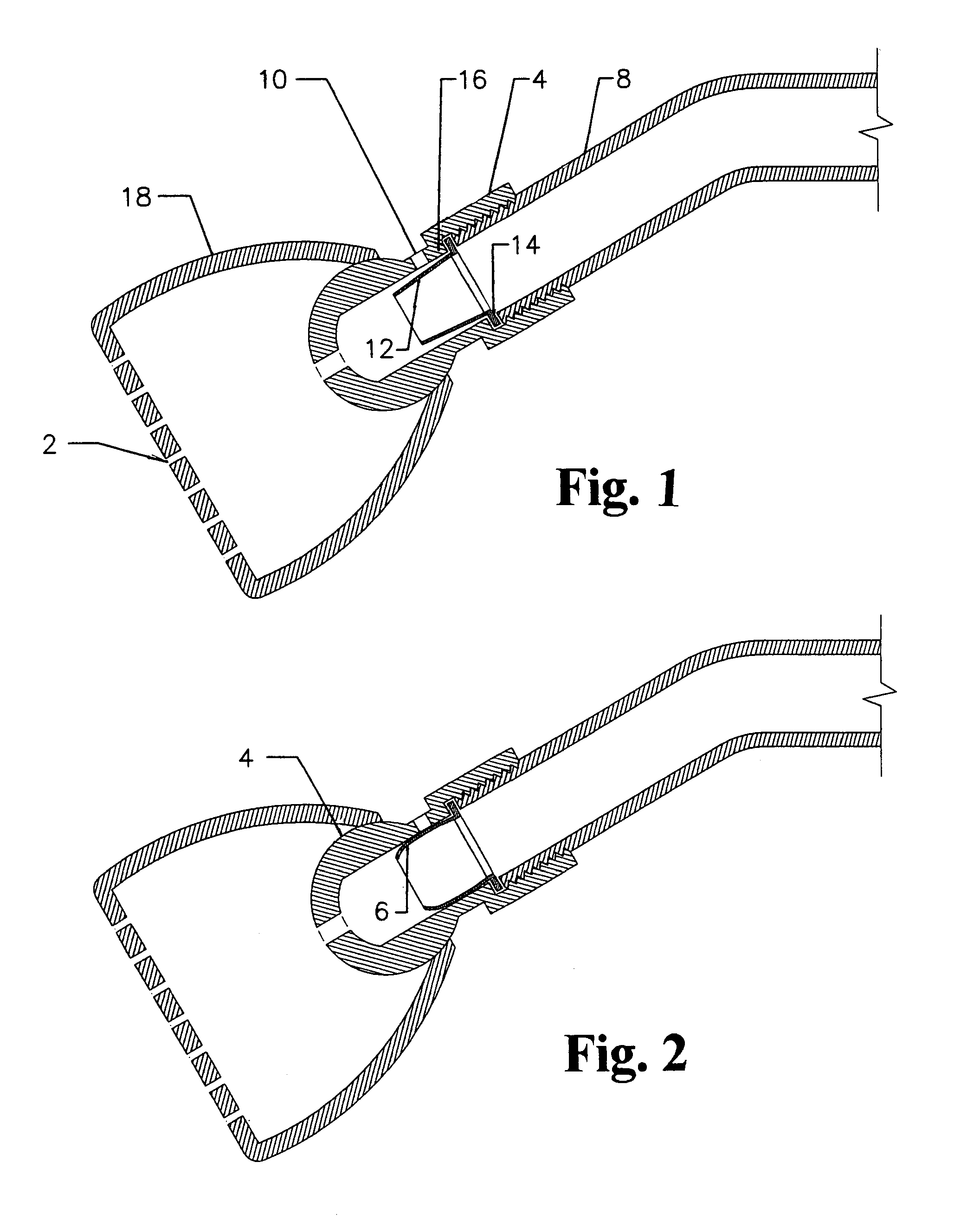
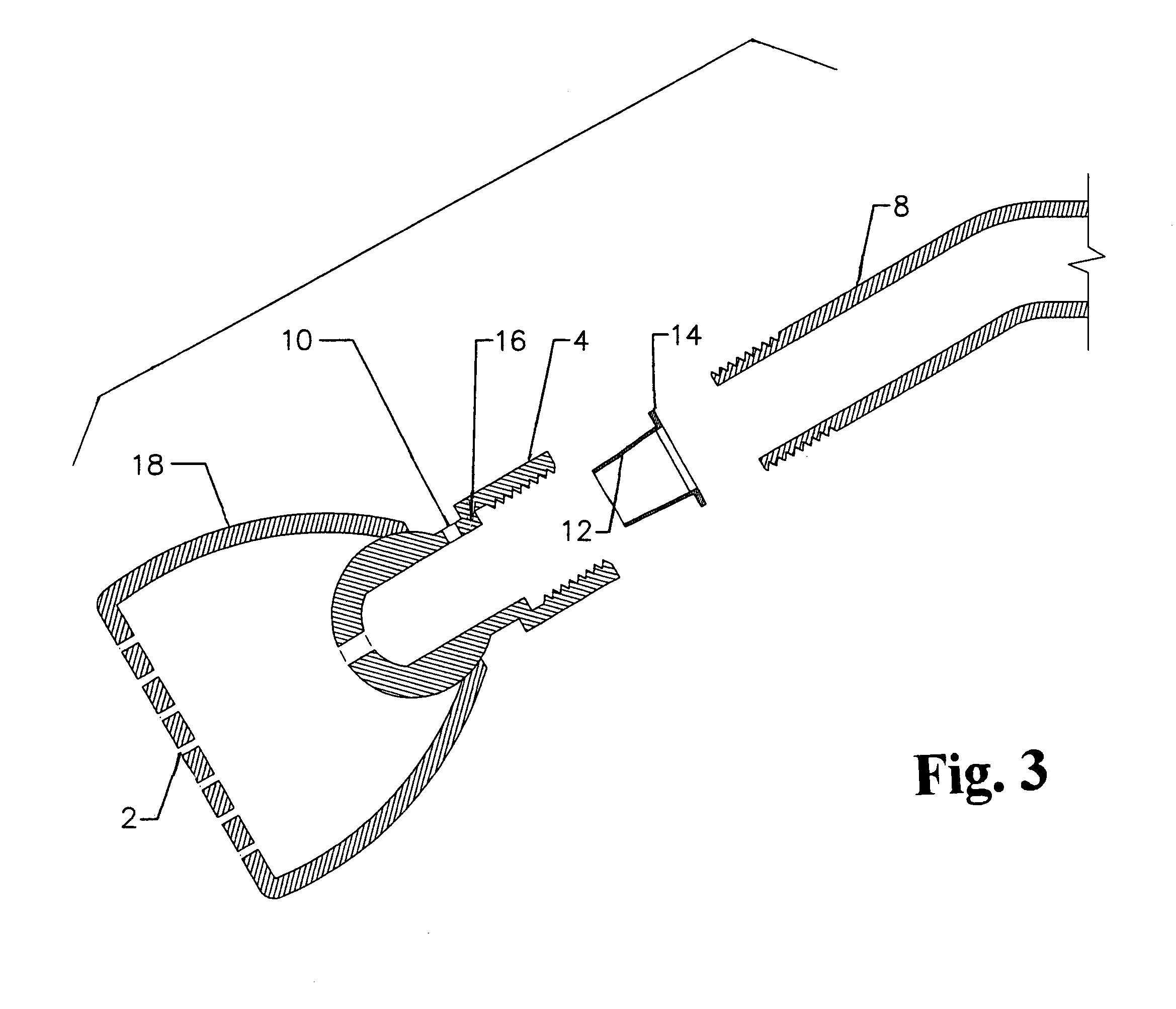
[0033]As viewed in FIG. 1 the inventive non-clogging showerhead device includes showerhead 18 with ball-adapter 4 defining a water pathway, with an upstream pathway portion and downstream pathway portion, in open communication with a supply line 8 through which water will be directed to flow. An array of holes 2 are illustrated at a lower (or downstream) discharge area of showerhead 18, and egress of water flowing through ball-adapter 4 and into the showerhead 18. As is well known in the prior art, showerhead 18 is adjustably fitted to said ball-adapter 4 so as to be swivelably mounted thereon.

[0034]An upper portion of the ball-adapter 4 (generally upstream of the showerhead 18) includes an internally threaded portion configured to cooperatively interconnect with a complementary threaded terminal portion of water supply line 8 (at a downstream portion of said supply line 8). Adjacent said internally threaded portion of ball-adapter 4 is a shoulder rest 16 which may be integral with ...


PUM


Abstract

A showerhead facilitating draining of water retained following shut-off. The showerhead includes a housing swivelably fitted on a ball-adapter which in turn includes an integral threaded segment for attachment to a water feed line. An air pathway is formed to extend from inside to outside the ball-adapter where it opens to generally atmospheric pressure. A flexible check valve in the form of an annular skirt is retained by an integral ring portion where the ball-adapter is threaded to the feed line. Under water-flow pressure, the skirt expands, blocking the passage. Upon shut-off, the skirt withdraws, instantly opening the air passage. Opening the showerhead to atmospheric pressure relieves the normally occurring suction effect which keeps water from draining completely from the showerhead spray holes. Thus avoiding the widespread problem of trapped water slowly evaporating and leaving behind stubborn and unsightly mineral deposits that eventually build up to clog showerhead spray holes.

Description

CROSS REFERENCE TO RELATED APPLICATIONS[0001]This application is a Continuation-in-Part of Non-provisional patent application Ser. No. 10 / 731,280 filed Dec. 9, 2003 and now abandoned; in turn, entitled to the benefit of Provisional Patent Applications Ser. No. 60 / 433,102 filed Dec. 13, 2002 and Ser. No. 60 / 454,740 filed Mar. 15, 2003, all of which applications in their entirety are incorporated herein. All benefits of priority of the afore-referenced patent applications are hereby claimed under 35 USC 120 and 35 USC 119(e), respectively.STATEMENT REGARDING FEDERALLY SPONSORED RESEARCH OR DEVELOPMENT[0002]Not applicable.REFERENCE TO SEQUENCE LISTING[0003]Not applicable.REFERENCE TO MICROFICHE APPENDIX[0004]Not applicable.BACKGROUND OF THE INVENTION[0005]This invention relates to showerheads and other similar water flow outlets.[0006]The present invention relates particularly to showerheads typically utilized in residential and hotel bathrooms, sports-related shower facilities and oth...

Claims


Application Information

Patent Timeline
Patent Type & Authority Patents(United States)
IPC IPC(8): B05B15/02F23D11/34F23D11/38F23D14/50E03C1/10F16K24/00B05B15/68
CPCB05B15/02E03C1/08B05B1/18E03C2201/70E03C2001/082B05B15/067B05B15/50B05B15/654Y10T137/3294
Inventor FRAZEE, JOHN S.
Owner FRAZEE JOHN S
Learn More