Cooling arrangement

a cooling arrangement and cooling technology, applied in the field of cooling arrangement, can solve the problems of inability to remove generated heat to a sufficient degree, considerable structural cost outlay, and inability to achieve the effect of reducing the cost of operation and maintenan

Inactive Publication Date: 2008-09-23
RITTAL RES ELECTRONICS SYST GMBH & CO KG
View PDF25 Cites 41 Cited by
  • Summary
  • Abstract
  • Description
  • Claims
  • Application Information

AI Technical Summary

Benefits of technology

[0006]It is one object of this invention to provide a printed circuit board or plug-in module of any arbitrary layout with liquid cooling without substantially changing the layout or the fitting with electronic components.
[0010]In one embodiment, the component feed line and the component return-flow line have coupling elements attached at the ends of the coupling area. These form, together with the counter coupling elements of the feed line and the return-flow line attached at the end of the housing, a releasably coupled connection. With this arrangement, it is possible to directly couple a liquid-cooled printed circuit board or plug-in module to the feed line and to the return-flow line which are connected with the air-conditioning device. Thus, the electronic components to be cooled can be easily connected with a liquid cooling body through which liquid flows and which has a connector for the component feed line and a connector for the component return-flow line.
[0013]The coupling connection can be designed as a no-drip releasable and pluggable coupling to prevent cooling liquid from running out when pulling out the printed circuit board or plug-in module.

Problems solved by technology

Because the generated heat cannot be removed to a sufficient degree by known air cooling fans, cooling by coolants are employed.
With the known cooling arrangement it is not possible without a considerable structural cost outlay to use plug-in modules of any arbitrary layout and to provide them with liquid cooling.

Method used


Image

  • Cooling arrangement
  • Cooling arrangement
  • Cooling arrangement

Examples


Embodiment Construction

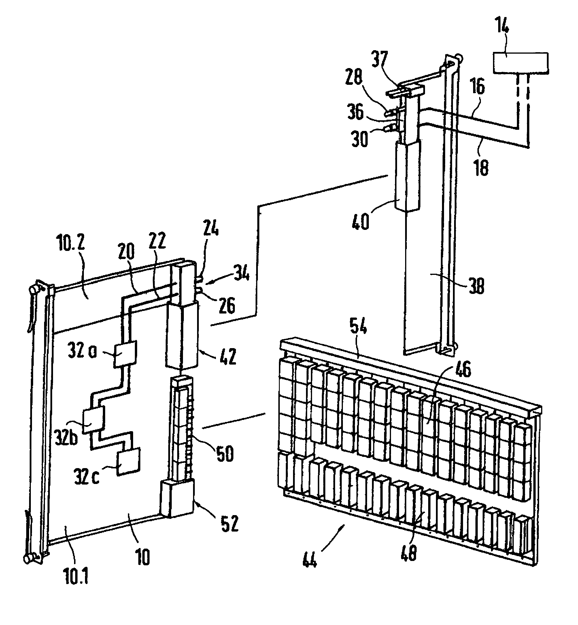
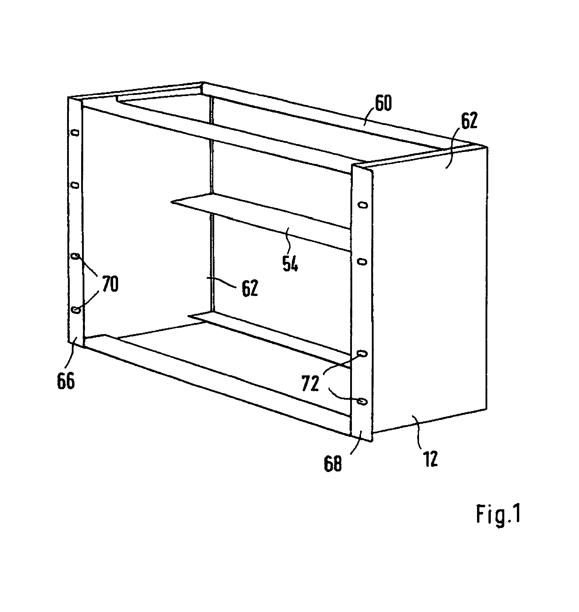
[0019]In a schematic-perspective plan view, FIG. 1 shows a component support 12 for receiving vertically arranged plug-in modules (not represented). The component support 12 has a support frame 60 with vertical and horizontal profiled frame sections. The two lateral elements of the component support 12 shown in FIG. 1 have lateral walls 62. A bottom plate and a cover plate are not installed. However, such plates can be attached in a perforated or non-perforated arrangement. A rear wall is also omitted. However, the component support 12 shows a transverse strut 54, embodied as a T-strut, in the area of or near its rear wall. The component support 12 is open at the front. There, plug-in modules can be inserted into guide rails (not represented) and, in the inserted state, can be fixed in place on the component support 12 by screw connections. On the left and right sides, the edge area of the front has a laterally protruding frame element 66 and 68, in which several through-bores 70 an...


PUM


Abstract

A cooling arrangement with a housing for receiving electronic printed circuit boards or plug-in modules, and with an air-conditioning device which is connected via a coolant-conducting feed line and a return-flow line with at least one electronic component, to be cooled, on the respective printed circuit board or the plug-in module. The feed line is coupled with at least one component feed line assigned to the electronic component. The return-flow line is coupled with at least one component return-flow line assigned to the electronic component. The printed circuit board or the plug-in module has an area for fitting electronic components and a coupling area for coupling the feed line with the component feed line and for coupling the return-flow line with the component return-flow line.

Description

BACKGROUND OF THE INVENTION[0001]1. Field of the Invention[0002]This invention relates to a cooling arrangement with a housing for receiving electronic printed circuit boards or plug-in modules, and with an air-conditioning device which is connected via a coolant-conducting feed line and a return-flow line with at least one electronic component, to be cooled, on the respective printed circuit board or plug-in module, wherein the feed line is coupled with at least one component feed line assigned to the electronic component, and the return-flow line is coupled with at least one component return-flow line assigned to the electronic component.[0003]2. Discussion of Related Art[0004]A cooling arrangement is known from European Patent Reference EP 1 448 040 A2. Plug-in modules, which are arranged on top of each other in a horizontal plane are housed in a switchgear housing. Built-in electronic devices are located on the plug-in modules, in particular CPUs of computer servers, which requi...

Claims


Application Information

Patent Timeline
Patent Type & Authority Patents(United States)
IPC IPC(8): H05K7/20
CPCG06F1/20H05K7/20772G06F2200/201
Inventor SONNABEND, WERNEROUSMANE, MOUHAMADOUBRAUN, WILFRIEDSCHAFFER, KURT
Owner RITTAL RES ELECTRONICS SYST GMBH & CO KG
Why Eureka
Try Eureka