
Lifting mechanism and health care equipment that incorporates the lifting mechanism

a technology of lifting mechanism and health care equipment, applied in the field of lifting mechanism, can solve the problems of bulky lifting mechanism and intrusive structure, and achieve the effect of facilitating the movement of patients

Inactive Publication Date: 2008-09-30
HUMAN CARE HC AB
View PDF18 Cites 94 Cited by
  • Summary
  • Abstract
  • Description
  • Claims
  • Application Information

AI Technical Summary

Benefits of technology

[0024]This relative upward and downward movement of the upper and lower support members makes the lifting mechanism suitable for use in a wide range of applications where differential lifting and lowering rates are required.
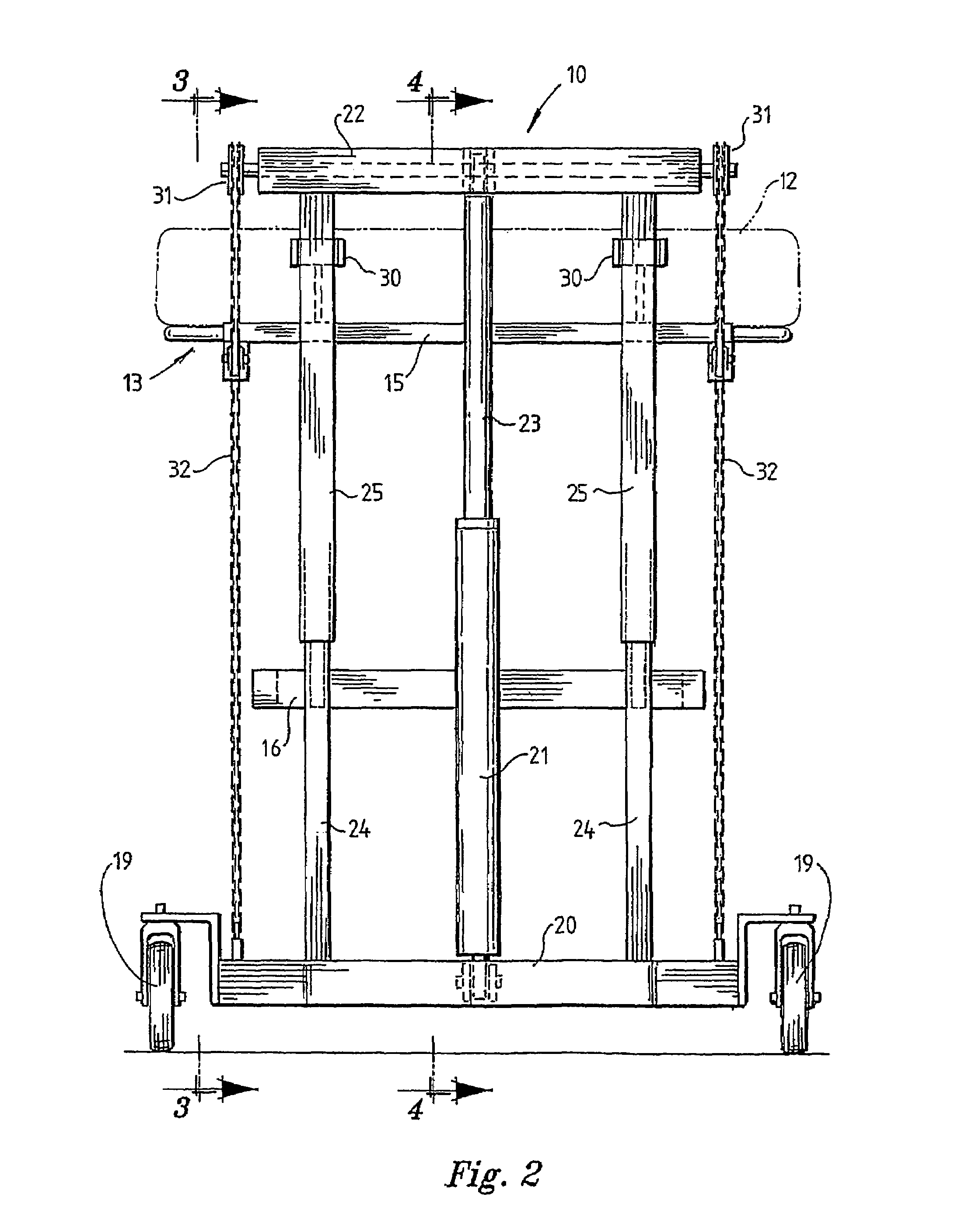
[0025]For example, one health care application is to facilitate moving patients from horizontal to sitting positions and supporting the patients in the sitting position by using the upper support member (for example via a sling) to support the torso of a patient and the lower support member (for example via a sling) to support the lower body of the patient. With this arrangement, operating the lifting mechanism results in the upper support member lifting the torso of the patient at a faster speed than the lower support member, with the result that the patient is moved to a sitting position as the patient is lifted upwardly.
[0044]Preferably the secondary patient support is a lower bed support frame which adds stability to the bed by creating a box frame with the primary support and the lifting mechanisms at each end of the bed.
[0051]By way of further example, in the case of the embodiment in which the sleeves are captured in guides located on the upper support member, the guides have a concave surface that allows the guides freedom to rotate on the sleeves thereby allowing for the relative movement between the sleeves and primary support when the lifting mechanisms at each end of the bed are adjusted to different heights.
[0055](c) the second section being provided at its end with a coaxially aligned third section which is shaped in cross-section to allow the sleeve, and thus the handlebar, to rotate around the third section thereby enabling the orientation of the handlebar relative to the angled bar to be changed by sliding the handlebar along the second section onto the third section, rotating the handlebar around the third section to a new orientation and sliding the handlebar back onto the second section with the handle orientated in a new direction.

Problems solved by technology

Consequently, the lifting mechanisms are usually bulky and intrusive structures that are difficult to pack, transport and assemble.

Method used


Image

  • Lifting mechanism and health care equipment that incorporates the lifting mechanism
  • Lifting mechanism and health care equipment that incorporates the lifting mechanism
  • Lifting mechanism and health care equipment that incorporates the lifting mechanism

Examples


Embodiment Construction

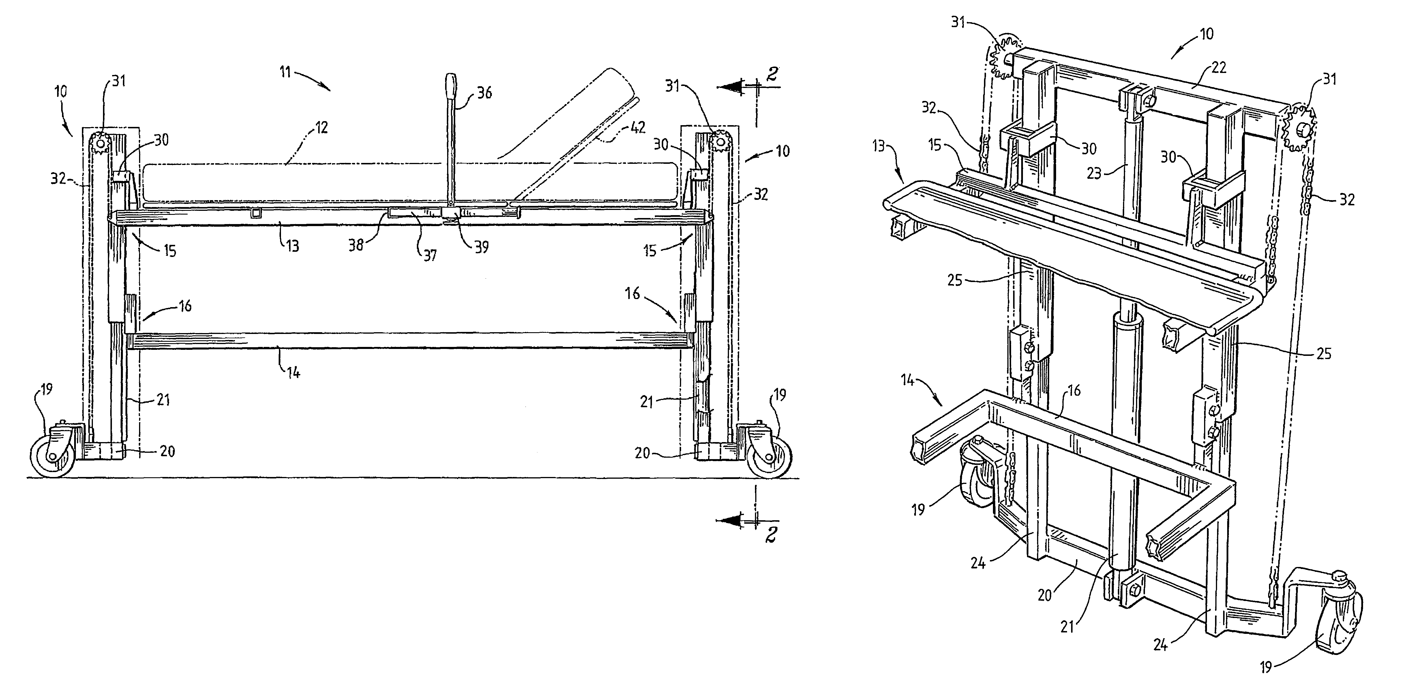
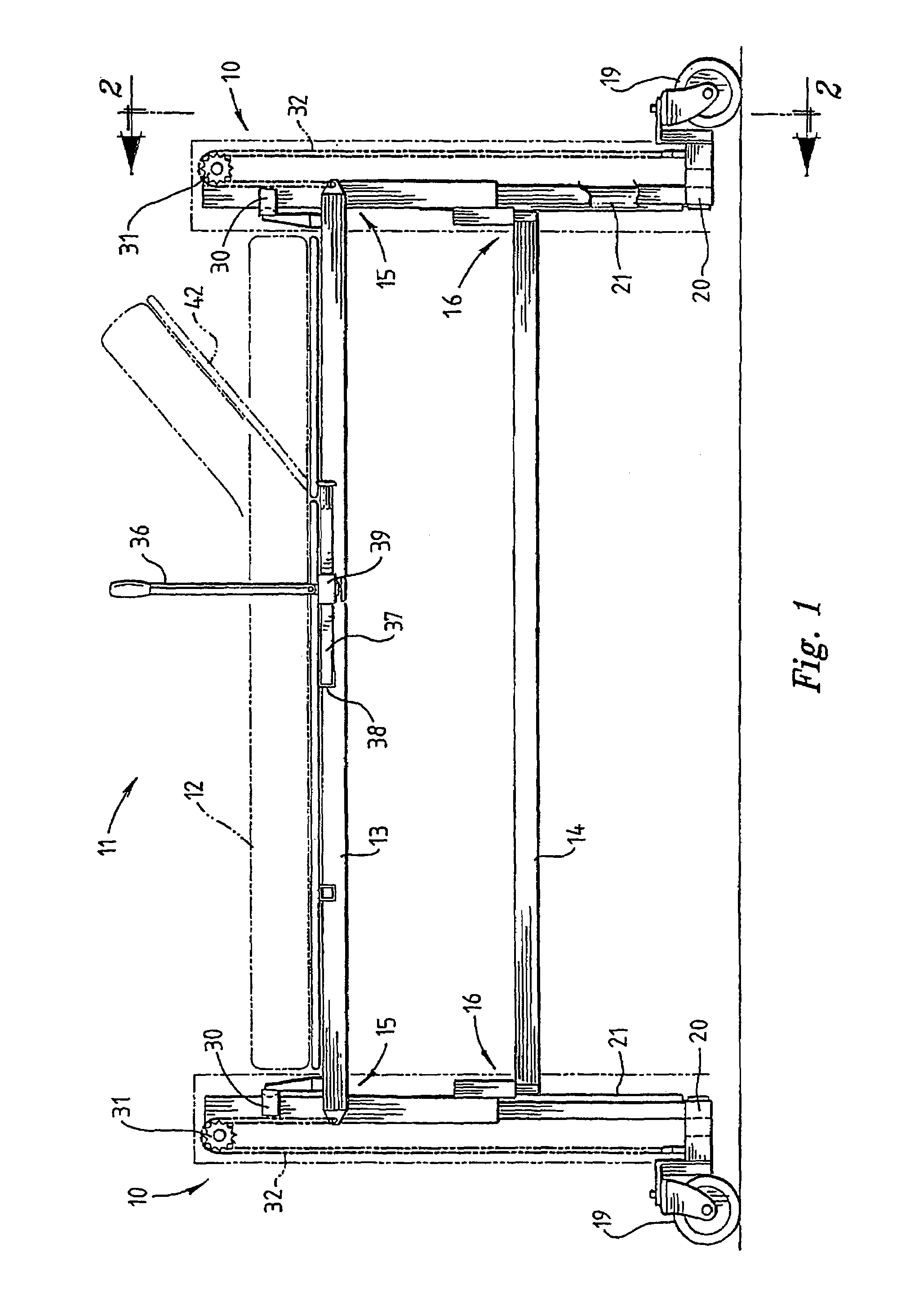
[0080]The invention relates to a lifting mechanism, which is described in the following preferred embodiment shown in FIGS. 1 to 12 in the context of health care equipment in the form of a height-adjustable bed, typically a hospital bed. The invention is not limited to this application.

[0081]Such a bed includes a mattress base positioned between two pedestal ends between which the mattress base may be raised or lowered. The bed may also feature, as illustrated in FIG. 1, a section 42 of the mattress base pivotally attached to the rest of the base so as to allow the section to tilt upwardly and serve as a backrest for a person lying in bed. A pump 43 located under the mattress base is usually used to operate the pivoting. FIG. 11 is a closer view of the pump and lever 44 used to pivot section 42 upwards.

[0082]In the present embodiment the mattress base is defined by an upper frame 13. The bed also includes a lower frame 14 spaced below the upper frame as illustrated in FIG. 1. In thi...


PUM


Abstract

Disclosed is a mechanism for raising and lowering a patient support including a base having two spaced posts extending upwardly, a sliding sleeve on each base post and a cross member fixed to and extending between the sleeves. An actuator is located between the base and the cross member to move the cross member vertically with respect to the base. A horizontal member located above the cross member is slidingly moveable with respect to the sleeves and includes guides to capture the sleeves. A pulley is provided on the cross member and supports a chain or belt, fixed to the base at a first end and at the other end to the horizontal support. As the actuator raises and lowers the cross member, the upper support is raised and lowered at a greater speed. On the base is a reversible fold down pole to assist the patient in raising and lowering themselves.

Description

BACKGROUND OF THE INVENTION[0001]1. Field of the Invention[0002]The invention relates to a lifting mechanism adapted for use in a wide range of applications.[0003]One particular, although by no means the only, application for the lifting mechanism of the invention is in the field of health care equipment to raise and lower patients. Accordingly the invention also relates to health care equipment that incorporates the lifting mechanism.[0004]In particular, the invention relates to a pedestal lifting mechanism located at the head and foot of a height-adjustable bed, such as a hospital bed, to raise and lower a bed mattress base.[0005]The invention also relates to a reversible, fold-down patient self-assist pole to be fitted to health care equipment.[0006]The following discussion focuses on health care equipment. However, it is noted that the invention is not limited to this application.[0007]2. Description of the Related Art[0008]Lifting devices for lifting patients and invalids are e...

Claims


Application Information

Patent Timeline
IPC IPC(8): A47B7/00A47C31/00A47C19/04B66F7/04A61G7/00A61G7/012A61G7/015A61G7/018A61G7/053A61G7/10B66F7/02B66F7/22
CPCA47C19/045A61G7/005A61G7/012A61G7/1017A61G7/1019A61G7/1046A61G7/1055A61G7/1057A61G7/015A61G7/018A61G2200/32A61G7/053
Inventor MCCRIMMON, BARRY EDWARD
Owner HUMAN CARE HC AB
Learn More