

Frame for a table top
a table top and frame technology, applied in the field of tables, can solve the problems of awkward or difficult to move the table, the table tops constructed from wood or metal are also relatively expensive, and the table tops constructed from wood or metal are also awkward or difficult to mov
- Summary
- Abstract
- Description
- Claims
- Application Information
AI Technical Summary
Benefits of technology
Problems solved by technology
Method used
Image

Examples
Embodiment Construction
[0014]A need therefore exists for a table that eliminates or diminishes the above-described disadvantages and problems.
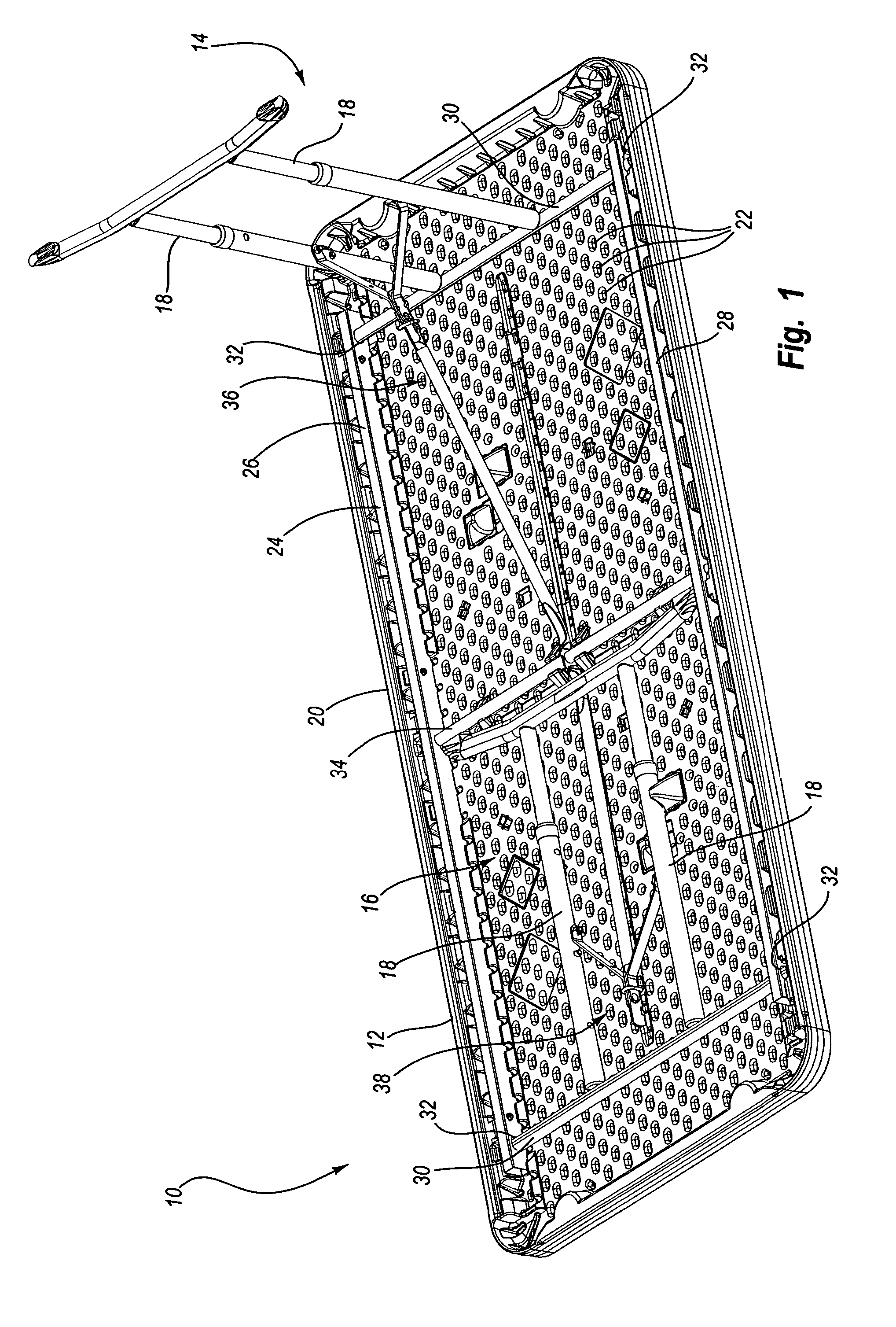
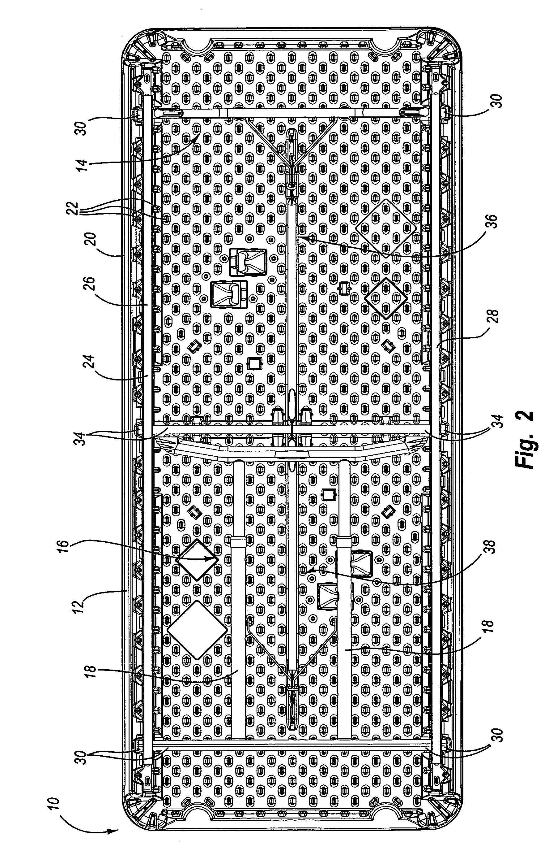
[0015]One aspect is a table that may include one or more legs or leg assemblies that can be moved between an extended or use position and a collapsed or storage position. When the legs are in the extended or use position, then the legs may support a table top above a surface such as the floor. On the other hand, when the legs are in the collapsed or storage position, then the table may be easier to move and / or transport.
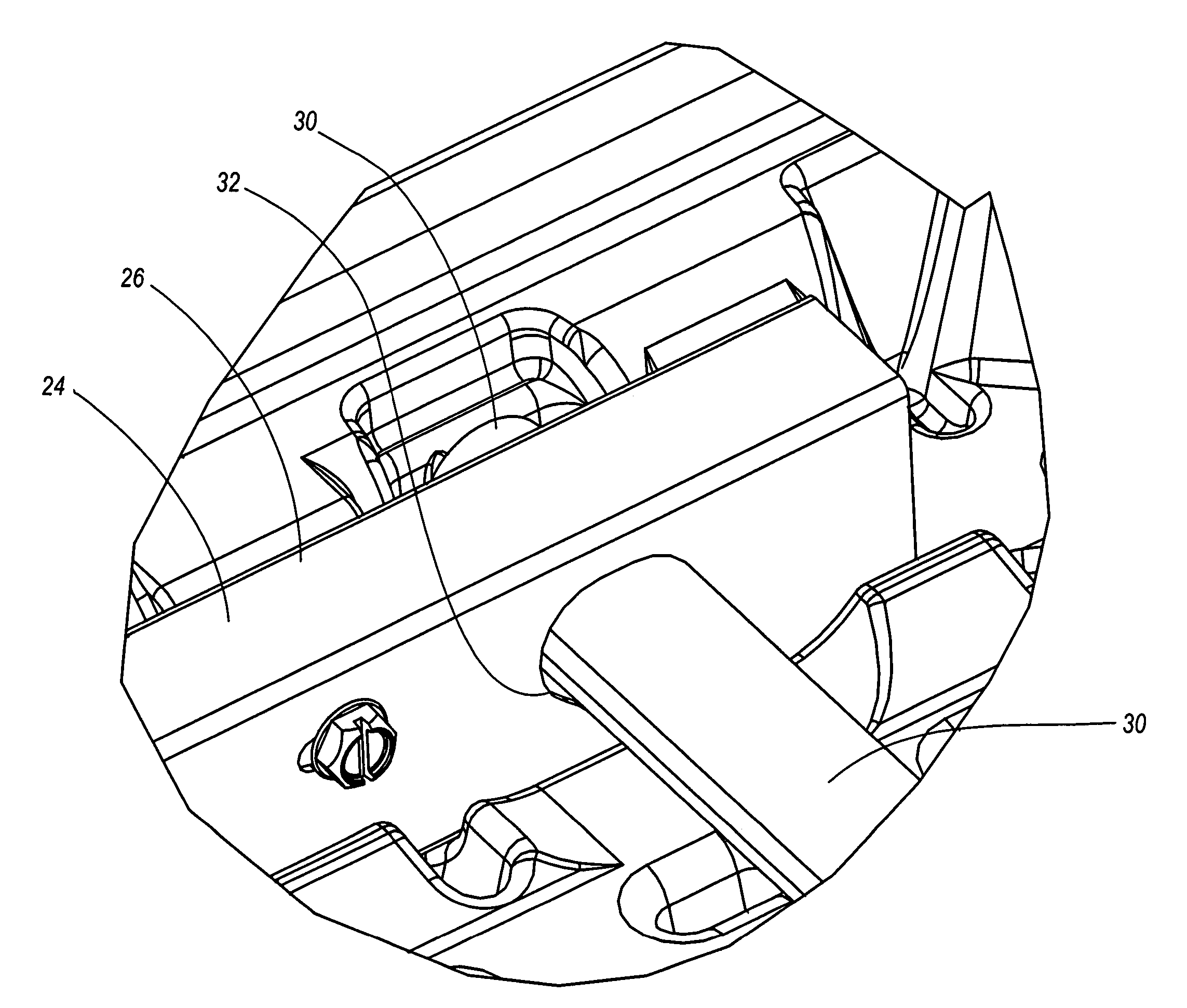
[0016]Another aspect is a table that may include a frame. The frame may be attached to the table top and the frame may be sized and configured to support the table top and / or allow the legs to be attached to the table top. For example, the frame may include one or more side rails and one or more cross bars may be connected to the side rails of the frame. The legs may be connected to the cross bars and the cross bars may be pivotally or otherwise conn...
PUM
 Abstract
Description
Claims
Application Information