
Chain cover and slat conveyor using the same

a chain conveyor and slat technology, applied in the direction of conveyors, conveyor parts, transportation and packaging, etc., can solve the problems of difficult to increase the width of the conveying surface of goods, limited application of the chain conveyor obtained, etc., to achieve high conveying stability, low cost, and ensure the effect of goods protection

Inactive Publication Date: 2008-09-30
YAMAMOTO MASAKAZU
View PDF9 Cites 5 Cited by
  • Summary
  • Abstract
  • Description
  • Claims
  • Application Information

AI Technical Summary

Benefits of technology

[0007]If a wide goods conveying surface can be formed by use of chain covers, a more inexpensive chain conveyor than a roller conveyor can be provided, so that it becomes possible to convey by an inexpensive chain conveyor goods which have heretofore been conveyed by a roller conveyor. Also, a chain conveyor formed by using chain covers can provide functionality which is not so different from the functionality of a known slat conveyor, and can provide improved conveying stability in comparison with the conveying by a roller conveyor.
[0014]The chain cover can be provided at low cost if it is made of a resin by integral molding. By combining with a number n of roller chains, a more inexpensive slat conveyor than a roller conveyor can be formed. A slat conveyor can provide higher conveying stability than a roller conveyor because it has a flat conveying surface, so that goods protection can be assured.
[0015]Also, it is possible to change the width of goods conveying surface freely by changing the number n of chains and top plates used, thereby solving the problem of limited application of conveyors.

Problems solved by technology

However, with such chain covers, a chain conveyor having a wide goods conveying surface cannot be formed, so that the application of the chain conveyor obtained is limited.
Also, although the width of the goods conveying surface can be increased by extending both ends of the top covers sidewise, it is difficult to increase the width of the goods conveying surface drastically with this method because the length of the extended portion is limited to assure strength.

Method used


Image

  • Chain cover and slat conveyor using the same
  • Chain cover and slat conveyor using the same
  • Chain cover and slat conveyor using the same

Examples


Embodiment Construction

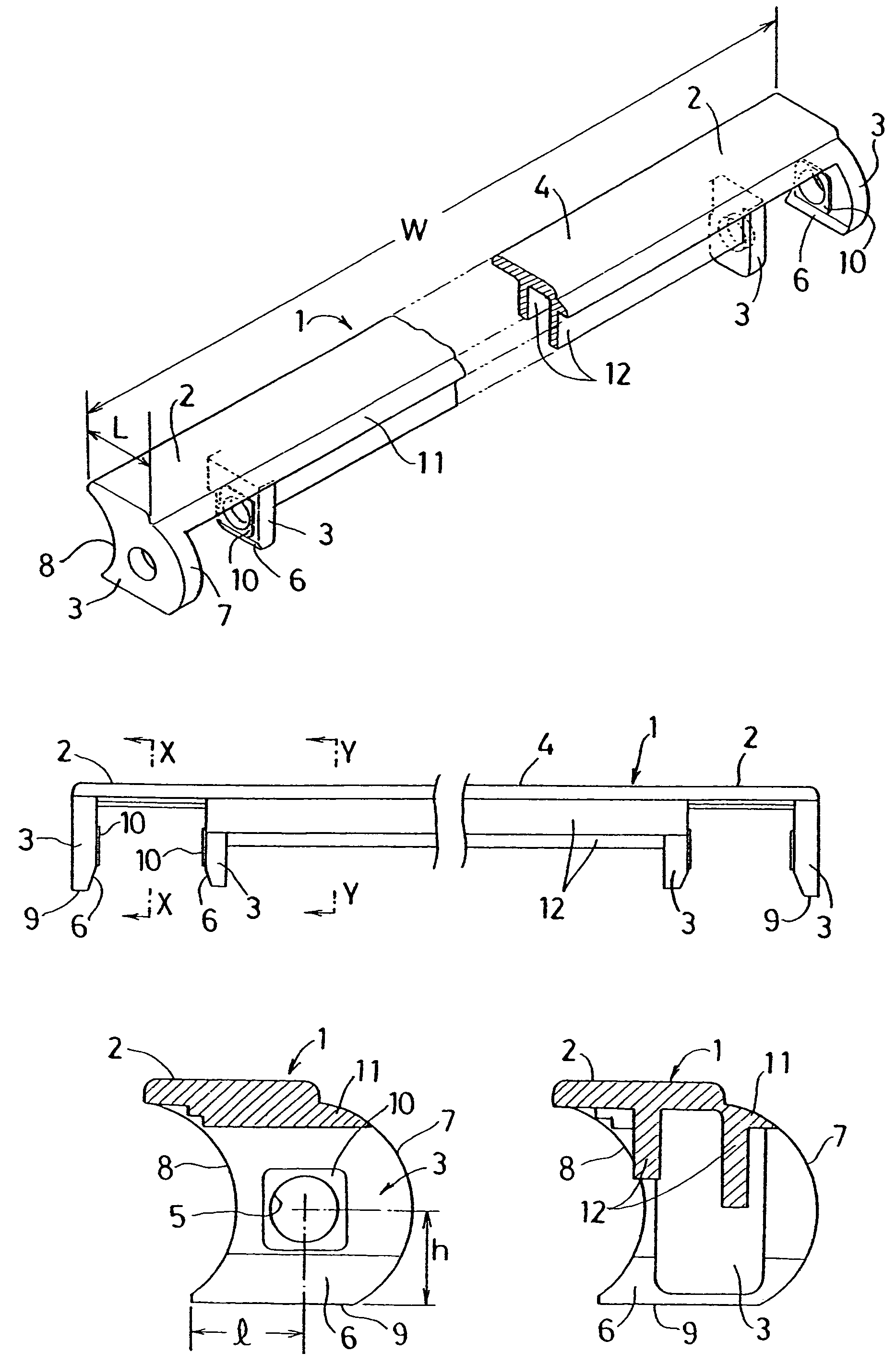
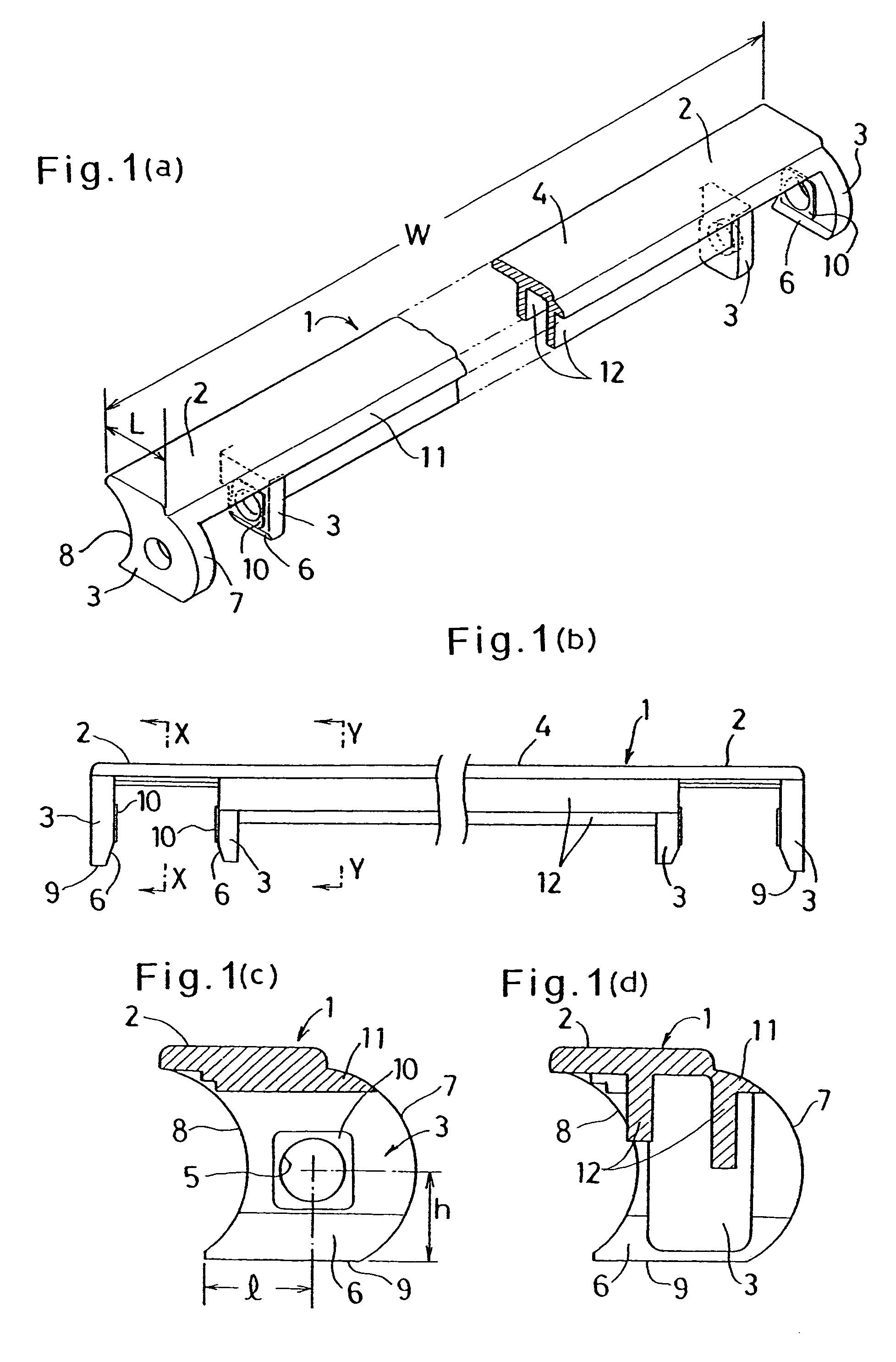
[0025]Hereinbelow, embodiments of this invention are described with reference to the accompanying drawings FIGS. 1 to 6. Chain covers 1 shown in FIG. 1 are combined with two endless roller chains arranged in parallel to form a slat conveyor. Each chain cover 1 includes as many top covers 2 as there are chains, side covers 3 hanging down from both ends of each top cover 2, and a coupling plate 4 coupling the top covers 2 together. The chain cover 1 shown here is made integrally of a resin by injection molding and can be made at low cost. But it may be a metal casting.

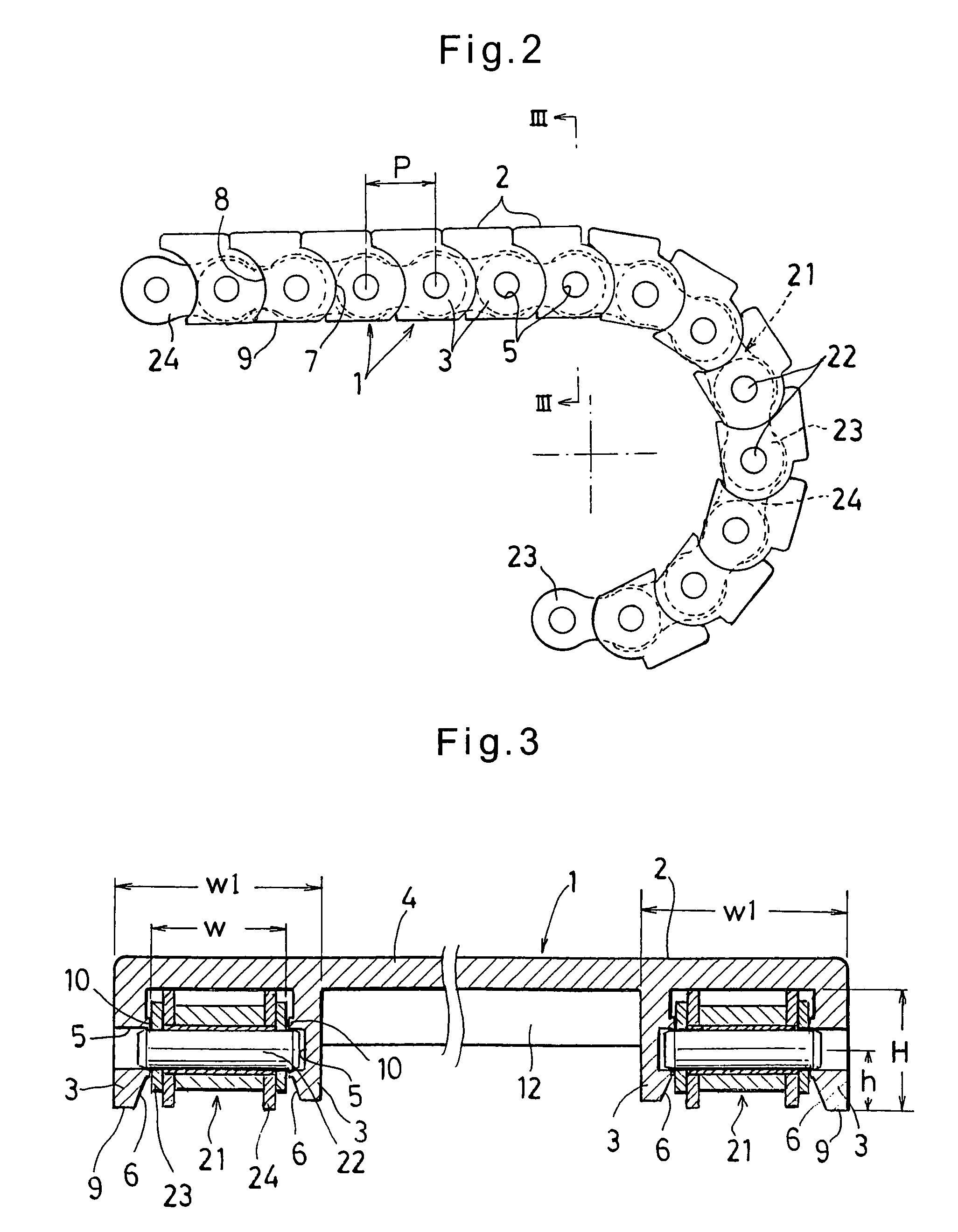
[0026]The length L of each top cover 2 is substantially equal to a chain pitch P (see FIG. 2). The width W1 of each top cover 2 is of a size proportional to one roller chain. Particularly, as shown in FIG. 3, the width W1 is set to be substantially equal to the width w of each roller chain 21 covered by the top cover 2 plus the thicknesses of the side covers 3 at both ends of the top cover.

[0027]Each side cover 3 has a s...


PUM


Abstract

A chain cover includes side covers each formed with a shaft hole for receiving a coupling pin of a roller chain, two top covers each having a length substantially equal to a chain pitch of the roller chain, and a coupling plate coupling the top covers adjacent to each other. The side cover at each end of the chain cover has a convexly arcuate front edge concentric with the shaft hole and a concavely arcuate rear edge similar to the front edge, and the coupling plate and two top covers cooperate to form a slat. A plurality of these chain covers can be mounted on a plurality of parallel roller chains to cover the top and sides of each roller chain and form a flat goods conveying surface between the roller chains, thereby forming a slat conveyor which is less expensive than a roller conveyor and provides excellent conveying stability.

Description

BACKGROUND OF THE INVENTION[0001]1. Technical Field[0002]This invention relates to chain covers mounted on a plurality of roller chains arranged in parallel so as to cover the top and sides of the roller chains and form a flat goods conveying surface between the roller chains, and a slat conveyor formed by the chain covers.[0003]2. Background Art[0004]A prior art chain cover of this type is disclosed in JP Patent laid-open publication 2001-315936. The chain cover shown in JP Patent laid-open publication 2001-315936 includes a top cover which is a flat plate having a length about equal to the chain pitch, and side covers hanging from both ends of the top cover. The side covers serve to cover both sides of the roller chain and each side cover is formed with a shaft hole in which one end of a coupling pin of the roller chain is received, a convexly arcuate front edge which is concentric with the shaft hole, a concavely arcuate rear edge which corresponds to the front edge, and a tapere...

Claims


Application Information

Patent Timeline
Patent Type & Authority Patents(United States)
IPC IPC(8): B65G17/06
CPCB65G17/067B65G17/42B65G2201/02
Inventor YOSHIDA, EIJI
Owner YAMAMOTO MASAKAZU
Learn More