Multi-row rubber chain pneumatic jacking transfer machine

A technology of lifting and transferring loads and rubber, which is applied to conveyor objects, transportation and packaging, etc., can solve the problems of inconsistent cylinder synchronization, low conveying stability, and large space occupation, so as to improve conveying stability and conveying stability. The effect of high performance and reduced space occupation

Inactive Publication Date: 2018-10-23
湖州龙辉物流机械设备有限公司
View PDF5 Cites 3 Cited by
  • Summary
  • Abstract
  • Description
  • Claims
  • Application Information

AI Technical Summary

Problems solved by technology

[0002] Pneumatic jacking and transfer machines are generally used to change the conveying direction of items, and send items into or out of the main conveying line from the fork, while the jacking method of conventional pneumatic jacking and transfer machines is to install the cylinder vertically on the jacking At the bottom of the platform, the jacking platform is directly driven up and down through the cylinder; this driving method will not only cause the synchronization of the cylinder during the jacking process to be inconsistent, resulting in unevenness of the jacking platform during lifting; and because the lifting force of the cylinder is uniform It is installed in the middle of the jacking platform, which will cause the heavy goods to be tilted according to the position of the goods when they are transported, which not only reduces the transport stability of the jacking and transfer machine, but also has the hidden danger of goods falling
In addition, the vertically arranged cylinders will increase the occupied space of the jacking and transferring machine, thus causing difficulties for users in model selection and arrangement
Therefore, the existing pneumatic jacking and transfer machines have the problems of low transport stability and large space occupation

Method used


Image

  • Multi-row rubber chain pneumatic jacking transfer machine
  • Multi-row rubber chain pneumatic jacking transfer machine
  • Multi-row rubber chain pneumatic jacking transfer machine

Examples


Embodiment Construction

[0015] The present invention will be further described below in conjunction with the accompanying drawings and embodiments, but not as a basis for limiting the present invention.

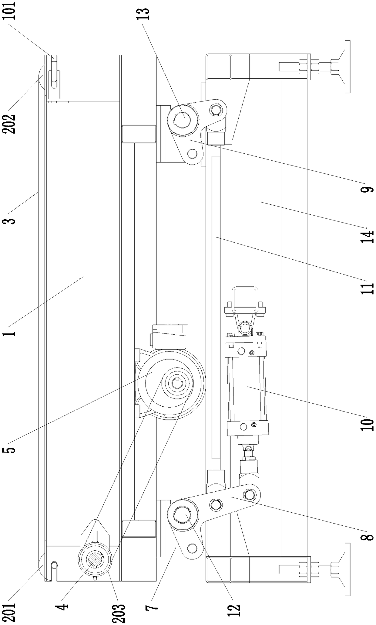
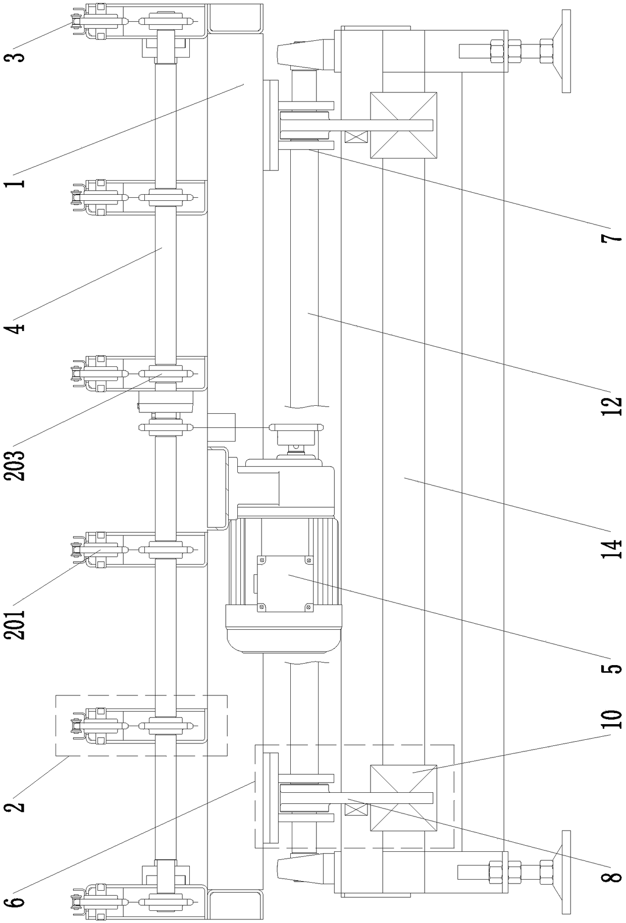
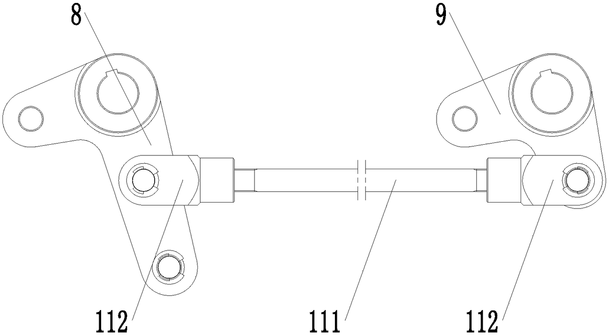
[0016] Example. Multi-row rubber chain pneumatic lifting transfer machine, constituted as figure 1 As shown, including a lifting bracket 1, a plurality of driving sprocket groups 2 are arranged side by side on the lifting bracket 1, and each driving sprocket group 2 is provided with a rubberized chain 3, and a plurality of driving sprocket groups 2 are driven The shafts 4 are connected to each other, and the driving shaft 4 is connected to the lifting bracket 1 in rotation. The middle part of the driving shaft 4 is connected with the drive motor 5 fixed on the lifting bracket 1 through a sprocket chain. The lifting device 6 includes lifting seats 7 fixed at both ends of the bottom of the lifting bracket, the lifting seats 7 on both sides are respectively connected with an active lifting arm 8 and a...


PUM


Abstract

The invention discloses a multi-row rubber chain pneumatic jacking transfer machine. The multi-row rubber chain pneumatic jacking transfer machine comprises a lifting bracket; a plurality of drive chain wheel sets are arranged on the lifting bracket side by side; each drive chain wheel set is provided with a rubber-covered chain; the multiple drive chain wheel sets are mutually connected through adrive shaft; a drive motor is connected to one side of a drive wheel; lifting devices are arranged on the two sides of the bottom of the lifting bracket; each lifting device comprises lifting seats fixed to the two ends of the bottom of the lifting bracket, and the lifting seats on the two sides are connected with a driving lifting arm and a driven lifting arm separately; a jacking-pushing cylinder is connected to the lower end of each driving lifting arm; and each driven lifting arm and the corresponding driving lifting arm are mutually connected through a connection shaft device. The multi-row rubber chain pneumatic jacking transfer machine has the characteristics of high conveying stability and small occupied space.

Description

technical field [0001] The invention relates to a pneumatic jacking and transferring machine, in particular to a multi-row rubber chain pneumatic jacking and transferring machine. Background technique [0002] Pneumatic jacking and transfer machines are generally used to change the conveying direction of items, and send items into or out of the main conveying line from the fork, while the jacking method of conventional pneumatic jacking and transfer machines is to install the cylinder vertically on the jacking At the bottom of the platform, the jacking platform is directly driven up and down through the cylinder; this driving method will not only cause the synchronization of the cylinder during the jacking process to be inconsistent, resulting in unevenness of the jacking platform during lifting; and because the lifting force of the cylinder is uniform It is installed in the middle of the jacking platform, which will cause the heavy goods to be tilted according to the positi...

Claims


Application Information

Patent Timeline
Patent Type & Authority Applications(China)
IPC IPC(8): B65G47/52
CPCB65G47/52
Inventor 陈龙
Owner 湖州龙辉物流机械设备有限公司
Why Eureka
Try Eureka