Automatic anchor bolt thermal shrinkage production line

A production line and anchor bolt technology, which is applied in the field of automatic heat shrinkable anchor bolt production line, can solve the problems of low production efficiency and high labor intensity of workers, and achieve the effect of improving work efficiency and reducing labor intensity

Pending Publication Date: 2021-08-31
CSIC HAIWEI ZHENGZHOU HIGH TECH CO LTD +1
View PDF11 Cites 3 Cited by
  • Summary
  • Abstract
  • Description
  • Claims
  • Application Information

AI Technical Summary

Problems solved by technology

[0007] The purpose of the present invention is to provide an automatic heat-shrinkable anchor bolt production line to solve the technical problems in the prior art ...

Method used


Image

  • Automatic anchor bolt thermal shrinkage production line
  • Automatic anchor bolt thermal shrinkage production line
  • Automatic anchor bolt thermal shrinkage production line

Examples


specific Embodiment 1

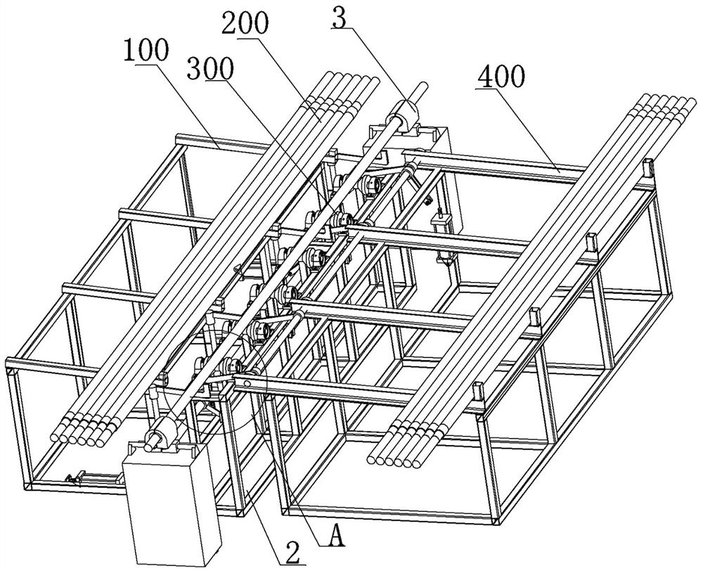
[0051] In this example, if Figure 1 to Figure 8 As shown, the anchor bolt automatic heat shrink production line includes a feeding unit 100, a heat shrink unit 300, and a material receiving unit 400 arranged in sequence along the front and rear directions. When in use, the anchor bolt 200 stored on the feeding unit 100 is used The single anchor bolts are transported one by one to the single anchor bolt processing position 301 of the heat shrink unit 300, and the single anchor bolt 200 is heat-shrinked by the heating machine 3 according to the predetermined production cycle. 200 is transferred to the material receiving unit 400 to realize the automatic heat shrinking processing of the anchor bolt 200.

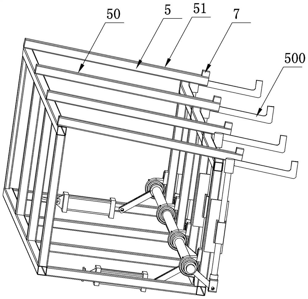
[0052] The feeding unit 100 is used to store the anchor bolts 200 to be heat-shrinked, and the specific structure is as follows: figure 1 , figure 2 , image 3 and Figure 8 As shown, the feeding unit 100 includes a feeding platform 5 and a feeding mechanism 500, and the f...

specific Embodiment 2

[0072] The main difference between it and Embodiment 1 is that in Embodiment 1, the feeding platform of the feeding unit has a feeding support surface, which is convenient for arranging multiple anchor bolts in a single layer. In this embodiment, the feeding unit can also be connected to other feeding production lines, and the single anchor bolt is delivered by the feeding production line, and then the single anchor bolt is transferred to the single anchor bolt processing position of the heat shrinking unit by the feeding mechanism, so as to realize heat shrinkage. shrink processing.

specific Embodiment 3

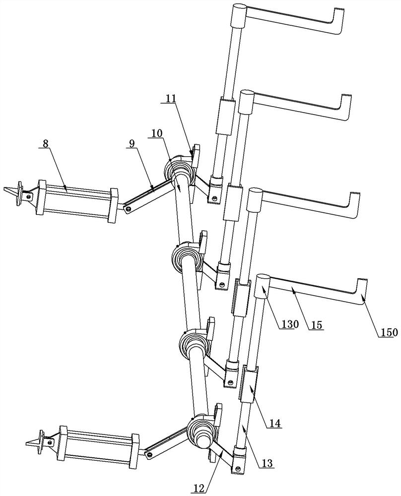
[0074] It differs from Embodiment 1 mainly in that: in Embodiment 1, the feeding mechanism includes a plurality of feeding racks, and each feeding rack includes a lifting part and an inclined guide rod respectively, and each inclined guide rod is correspondingly arranged on Between the corresponding two V-shaped wheels, correspondingly, a plurality of unloading levers of the unloading mechanism are also correspondingly located between the corresponding two V-shaped wheels. In this embodiment, two inclined guide rods of the loading mechanism and two blanking levers of the unloading mechanism can be provided respectively, and the two inclined guide rods and the two blanking levers are correspondingly located on the two sides of all V-shaped wheels. side to form a two-point support. At this time, in order to improve the stability of the support, the width of the guide rod and the blanking lever can be properly tilted.

[0075] Of course, in other embodiments, three inclined guide...


PUM


Abstract

The invention relates to an automatic anchor bolt thermal shrinkage production line. The automatic anchor bolt thermal shrinkage production line comprises a feeding unit, a thermal shrinkage unit and a material receiving unit; the feeding unit is used for storing anchor bolts to be subjected to thermal shrinkage processing; the thermal shrinkage unit comprises a thermal shrinkage rack and a heating device; the thermal shrinkage rack is provided with a single anchor bolt processing position; the single anchor bolt processing position is used for supporting and placing a single anchor bolt; the heating device is used for heating thermal shrinkage pipes at the two ends of the single anchor bolt to achieve thermal shrinkage processing; the material receiving unit is used for collecting anchor bolts subjected to thermal shrinkage processing; a feeding mechanism is arranged at the rear end of the feeding unit and is used for conveying the anchor bolts to the single anchor bolt processing position one by one; and a discharging mechanism is arranged at the front end of the material receiving unit and is used for transferring the anchor bolts subjected to thermal shrinkage processing to the material receiving unit from the single anchor bolt processing position. The single anchor bolt is conveyed to the single anchor bolt processing position of the thermal shrinkage unit through a feeding structure, the thermal shrinkage pipes on the two sides of the anchor bolt are correspondingly heated through the heating device, and after heating is completed, the anchor bolt is transferred to the receiving unit through the discharging mechanism, so automatic thermal shrinkage processing of the anchor bolt is conveniently achieved.

Description

technical field [0001] The invention relates to an automatic heat-shrink production line for anchor bolts. Background technique [0002] The high-strength anchor bolt is the core component of the prestressed fan foundation. The two ends of the anchor bolt are threaded, and the middle is a polished rod section. The high-strength anchor bolt must also meet this requirement in terms of materials, protection and other technical measures. [0003] The anchor bolt body is made of metal material. Once the anchor bolt assembly is embedded in concrete, it needs to be guaranteed not to corrode for a long period of use (20-25 years). Therefore, the anti-corrosion of the anchor bolt becomes very important. In the prior art, the most common anti-corrosion methods are Dacromet or hot-dip galvanized anti-corrosion coating treatment and heat-shrinkable tube anti-corrosion methods on the anchor bolt surface. [0004] For anti-corrosion coatings, hot-dip galvanized anti-corrosion has certain...

Claims


Application Information

Patent Timeline
IPC IPC(8): B65B35/10B65B53/02B65B61/28B65B19/34
CPCB65B35/10B65B53/02B65B61/28B65B19/34
Inventor 王志敏王建楹白洁刘禹王自强丁永春杨中桂靳逸飞王家斌郭聪王小荷
Owner CSIC HAIWEI ZHENGZHOU HIGH TECH CO LTD
Why Eureka
Try Eureka