Outboard motor control system

a control system and motor technology, applied in the direction of steering initiation, special purpose vessels, vessel construction, etc., can solve the problems of insufficient perfonnanee of prior art auto-spanker, inability to freely change the confluence point of the stream, etc., to enhance the performance of the auto-spanker and improve the stability of the boat driving

Inactive Publication Date: 2008-09-30
HONDA MOTOR CO LTD
View PDF8 Cites 33 Cited by
  • Summary
  • Abstract
  • Description
  • Claims
  • Application Information

AI Technical Summary

Benefits of technology

[0009]An object of this invention is therefore to solve the foregoing issues and to provide an outboard motor control system that enables free adjustment of the stream confluence point of multiple outboard motors installed on a boat, thereby improving boat driving stability and providing enhanced auto-spanker performance.

Problems solved by technology

However, when the angle between the outboard motors is rigidly fixed by the tie bar in the conventional manner, the stream confluence point cannot be freely changed, so that the perfonnanee of the prior art auto-spanker is not satisfactory.

Method used


Image

  • Outboard motor control system
  • Outboard motor control system
  • Outboard motor control system

Examples


first embodiment

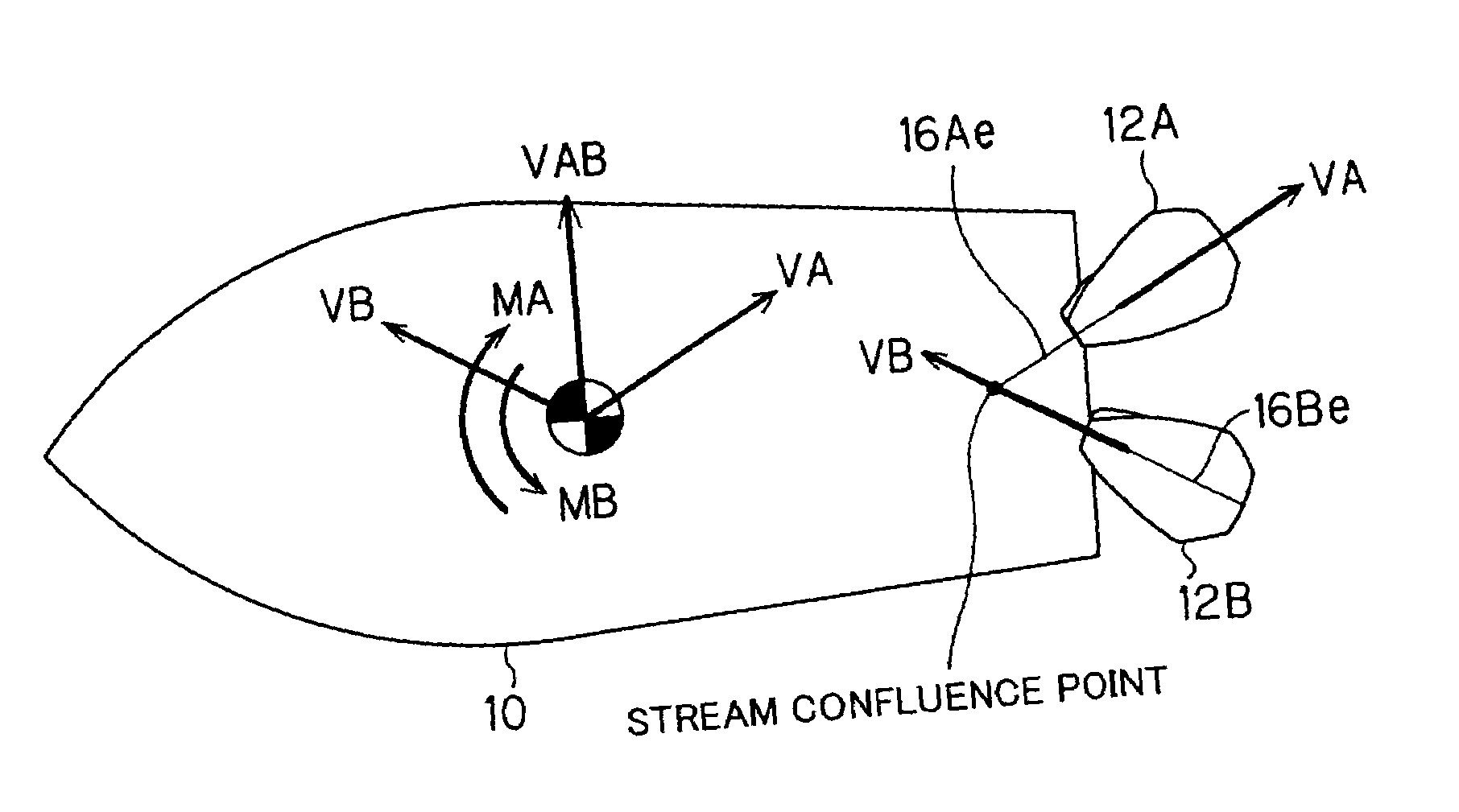
[0023]FIG. 1 is an overall schematic view of a boat (hull) and outboard motors equipped with an outboard motor control system according to this invention.

[0024]As shown in FIG. 1, a plurality of (two) outboard motors are mounted on the stern of a boat (hull) 10. In other words, the boat 10 has what is known as a multiple (dual) outboard motor installation. In the following, the starboard side outboard motor, i.e., outboard motor on the right side when looking in the direction of forward travel is called the “first outboard motor” and assigned the reference symbol 12A. The port side outboard motor, i.e., outboard motor on the left side when looking in the direction of forward travel is called the “second outboard motor” and assigned the reference symbol 12B.

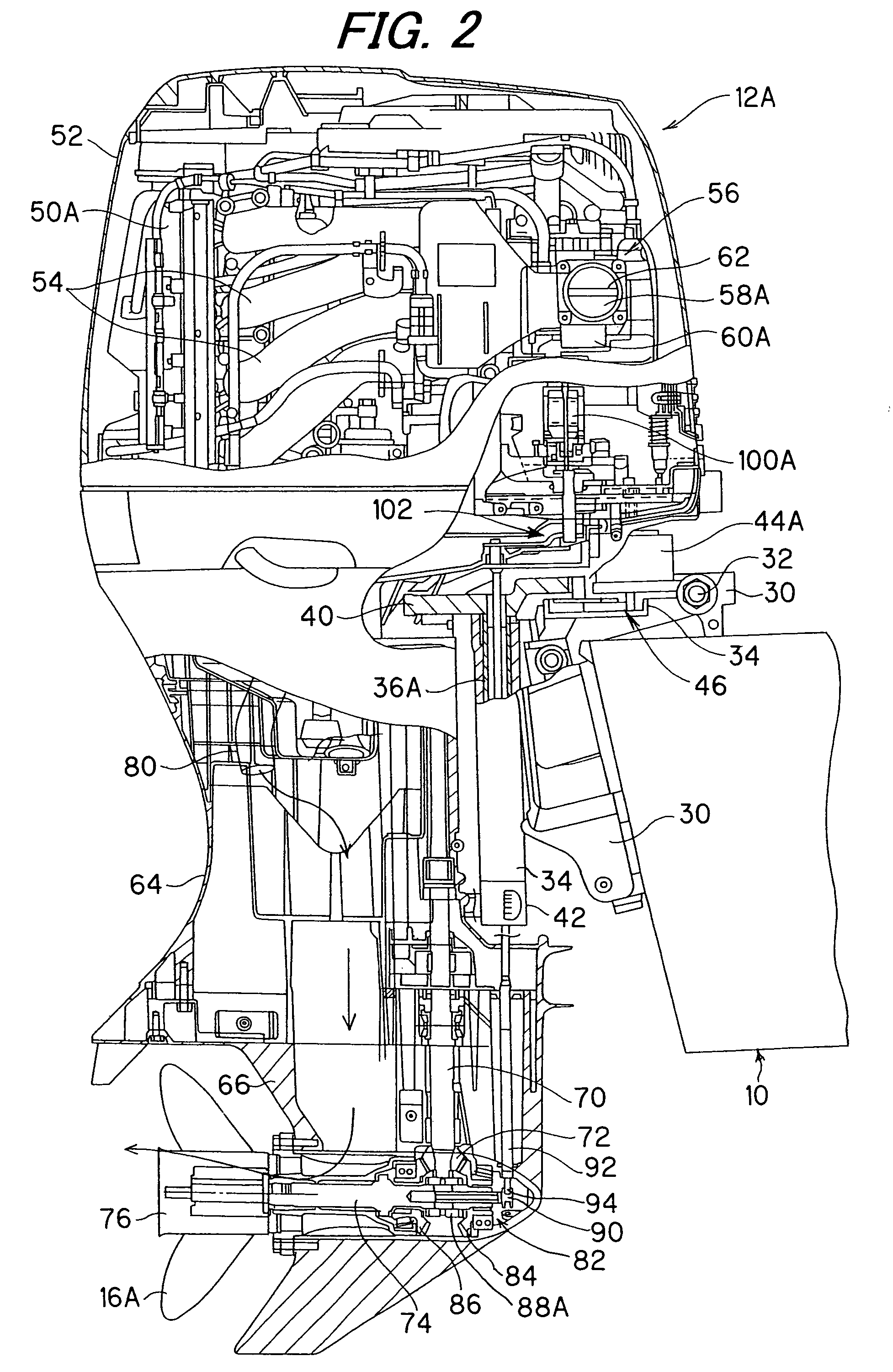
[0025]The first and second outboard motors 12A, 12B are equipped at their lower ends in the gravitational direction with propellers 16A, 16B and at their upper ends with internal combustion engines. The propellers 16A, 16B are rot...

second embodiment

[0081]An outboard motor control system according to this invention will now be explained.

[0082]FIG. 7 is a block diagram, similar to FIG. 3, but showing the outboard motor control system according to the second embodiment of this invention.

[0083]The second embodiment will be explained with focus on the points of difference from the first embodiment. As shown in FIG. 7, in the second embodiment the overall controller 124 installed on the boat 10 is replaced with a first controller 140A installed in and used exclusively for controlling the first outboard motor 12A and a second controller 140B installed in and used exclusively for controlling the second outboard motor 12B.

[0084]The outputs P1, P2 of the first and second lever position sensors 110, 112, the output θstr of the rotation sensor 114, the outputs Dw, Vw of the anemometer 116 and the output of the auto-spanker switch 26 are inputted to the first and second controllers 140A, 140B via a wire or wireless communication unit 142. ...


PUM


Abstract

In an outboard motor control system having two outboard motors each mounted on a stern of a boat, there is provided a controller that controls operation of steering actuators to regulate steering angles of the outboard motors such that lines extending from axes of rotation of the propellers of the outboard motors intersect at a desired point. With this, it becomes possible to freely adjust the stream confluence point of the outboard motors, thereby improving boat driving stability and providing enhanced auto-spanker performance.

Description

BACKGROUND OF THE INVENTION[0001]1. Field of the Invention[0002]This invention relates to an outboard motor control system, particularly to an outboard motor control system for controlling the operation of a plurality of outboard motors mounted on a boat (hull).[0003]2. Description of the Related Art[0004]When two or more outboard motors are mounted on the stern of a boat (hull) in what is known as a multiple outboard motor installation, the outboard motors are usually connected by a link called tie bar for enabling mechanically interconnected steering of the outboard motors, as taught in Laid-Open Patent Application No. Hei 8(1996)-276896, for example.[0005]In the case of multiple outboard motor installation, boat driving stability can be improved by making extensions of the outboard motors' propeller axes of rotation intersect at a predetermined distance (e.g., about 20 meters) rearward of the mounting location of the outboard motors. (In the following, the point of intersection o...

Claims


Application Information

Patent Timeline
Patent Type & Authority Patents(United States)
IPC IPC(8): B63H5/20B63H25/04
CPCB63H21/213B63H25/42B63H21/265B63H20/12B63H20/20B63H2020/003
Inventor YAZAKI, MAKOTONAKAYAMA, SHINSAKUTAKADA, HIDEAKI
Owner HONDA MOTOR CO LTD
Why Eureka
Try Eureka