Sleep state estimating device and program product

a technology of sleep state estimation and program product, which is applied in the field of sleep state estimation device and program product, can solve the problems of not being able to match the actual change in sleep state, not being able to provide only the suitable apparatus, and being unsuitable for daily use such as fitness equipment, etc., and achieves stable sleep estimation and less easily affected

Inactive Publication Date: 2008-09-30
SANYO ELECTRIC CO LTD
View PDF11 Cites 50 Cited by
  • Summary
  • Abstract
  • Description
  • Claims
  • Application Information

AI Technical Summary

Benefits of technology

[0011]The present invention has been made in view of the above, and an object of the present invention is therefore to provide a sleep state estimating device capable of estimating how deep or light a subject's sleep is easily with precision while using signals that are readily detected without restraining the subject.
[0012]The main feature of the present invention resides in that a sleep state is estimated based on a time-series oriented respiratory movement waveform which changes by the minute regularly and irregularly. A respiratory movement waveform can readily be detected without restraining a subject. The use of a respiratory movement waveform allows simple and accurate estimation of a sleep state.
[0014]A sleep state estimating device according to this aspect uses a time-series oriented waveform curve concerning respiration, and thus makes smooth sleep state estimation possible without restraining a subject too heavily. In addition, since a sleep state is estimated based on the shape of this waveform, an accurate sleep state can be learned and the precision of the sleep state estimation is high.
[0016]Measuring the shape of the time-series oriented waveform concerning respiration by its area in this manner makes it simpler to calculate an evaluation value determined in accordance with the waveform shape and makes it possible to track changes in waveform with precision. As a result, a sleep state can be estimated easily and accurately.
[0018]Using a dispersion value of inter-peak areas in this manner makes precise sleep state estimation possible. One dispersion value of inter-peak areas does not uniquely determine one sleep state since the body position and the like have to be factored in. Dividing a dispersion value of inter-peak areas by the square of the average of the inter-peak areas which could be greatly influenced by the body position and the like as described above effectively suppresses the influence that a change in body position and the like has over the evaluation value.
[0020]A sleep state estimating device according to still another aspect of the present invention estimates a sleep state at a given time point by collecting a sleep state value at regular intervals (a sleep state estimation result of a given period) and using the collected sleep state values of plural periods. According to this aspect, since a sleep state is estimated from plural periods of estimation results, stable sleep estimation is achieved which is less easily affected by a sudden rise or fall of sleep state value.

Problems solved by technology

However, the polysomnography requires a large-scale apparatus and can be used only at a site provided with measurement facilities such as a hospital, thereby being unsuitable for daily use such as use in fitness equipment.
In addition, the polysomnography can be used for judgment only by a qualified person, and it is not sufficient only that a suitable apparatus is available.
However, the above-described sleep estimation according to prior art has a problem with a low probability of matching the actual change in sleep state, and much lower accuracy than the polysomnography in judging the deep sleep and the light sleep.
Measurement by the electrocardiogram, however, has a drawback in that plural electrodes have to be attached directly to the skin of a subject, restraining the body of a person with the cords extending from each electrode to the measurement equipment.
On the other hand, a non-restraining sensor can only catch minute heart rate signals full of noises due to other elements than heartbeat.
Non-restraining measurement therefore needs FFT and filter computation processing for frequency analysis as well as signal amplification processing, which complicate the measurement process.

Method used


Image

  • Sleep state estimating device and program product
  • Sleep state estimating device and program product
  • Sleep state estimating device and program product

Examples


Embodiment Construction

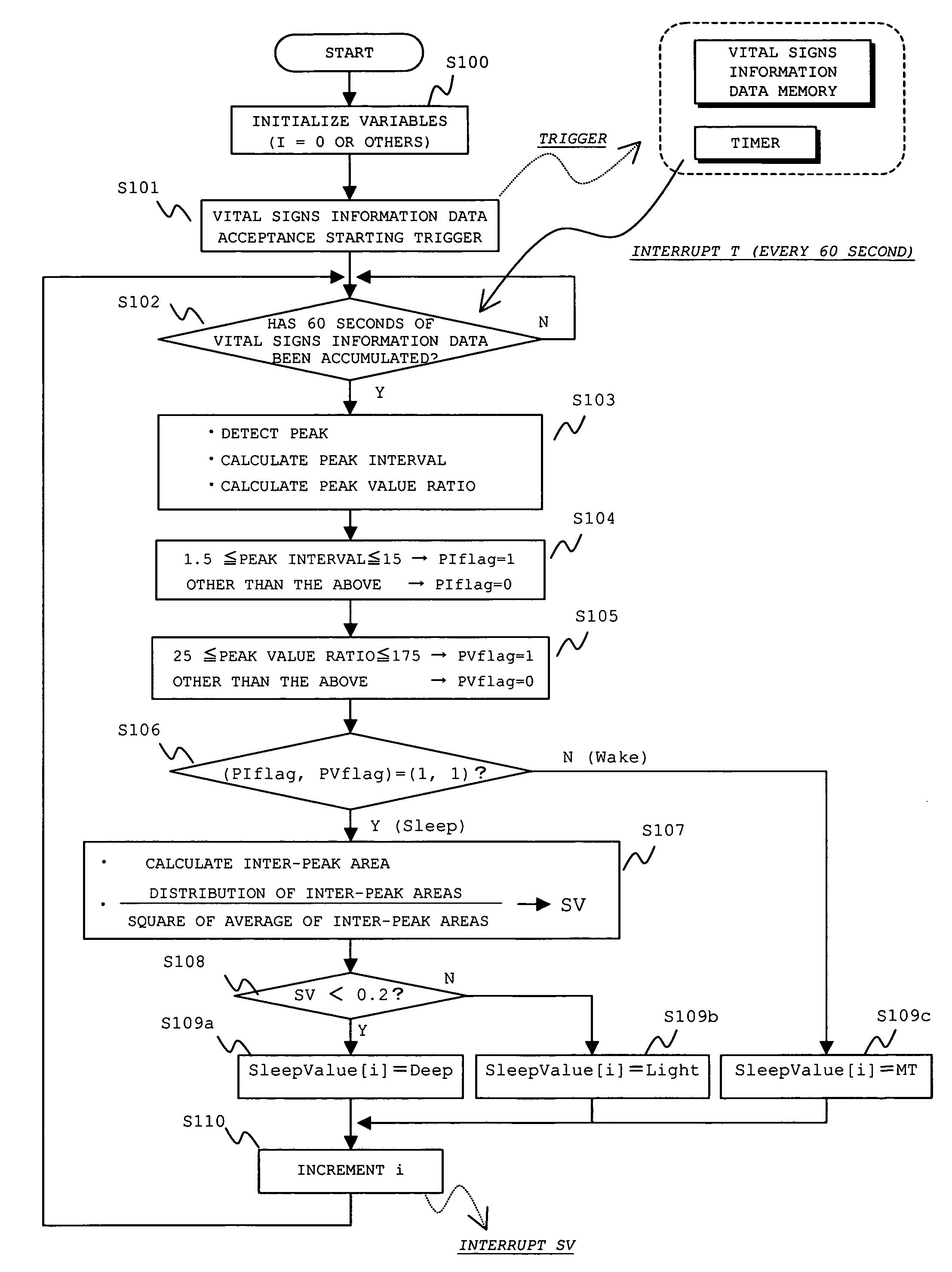
[0031]An embodiment of the present invention is described below with reference to the drawings.

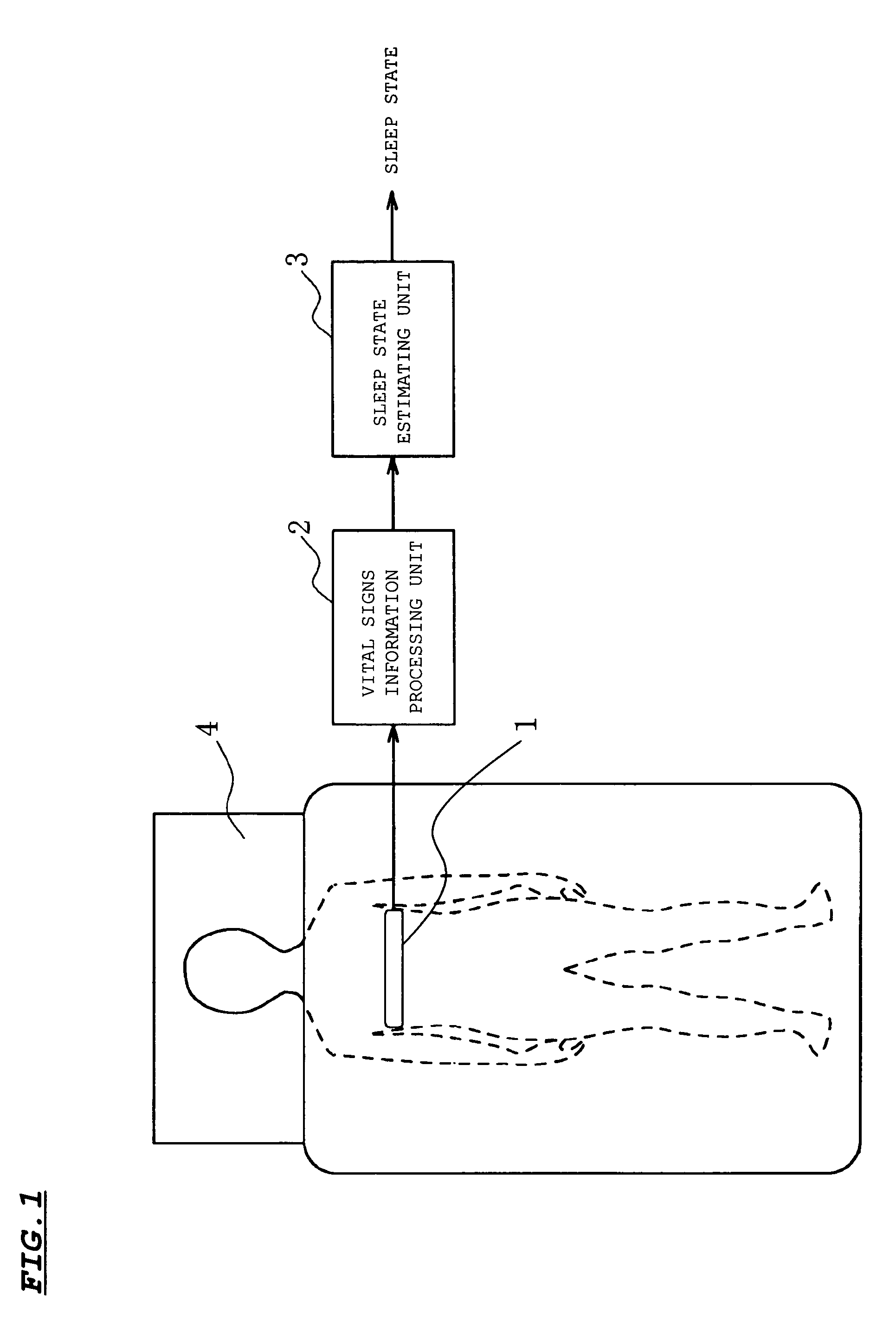
[0032]Referring to FIG. 1, a sleep state estimating device according to the embodiment of the present invention is composed of a respiratory band 1, which is one of vital signs information sensors, a vital signs information processing unit 2 including waveform obtaining means for obtaining a waveform curve that is a time-series oriented characteristic concerning respiration from data provided by the sensor, and a sleep state estimating unit 3 for estimating a sleep state. In FIG. 1, a person is lying on a mattress 4 with the respiratory band 1 attached to his / her upper body.

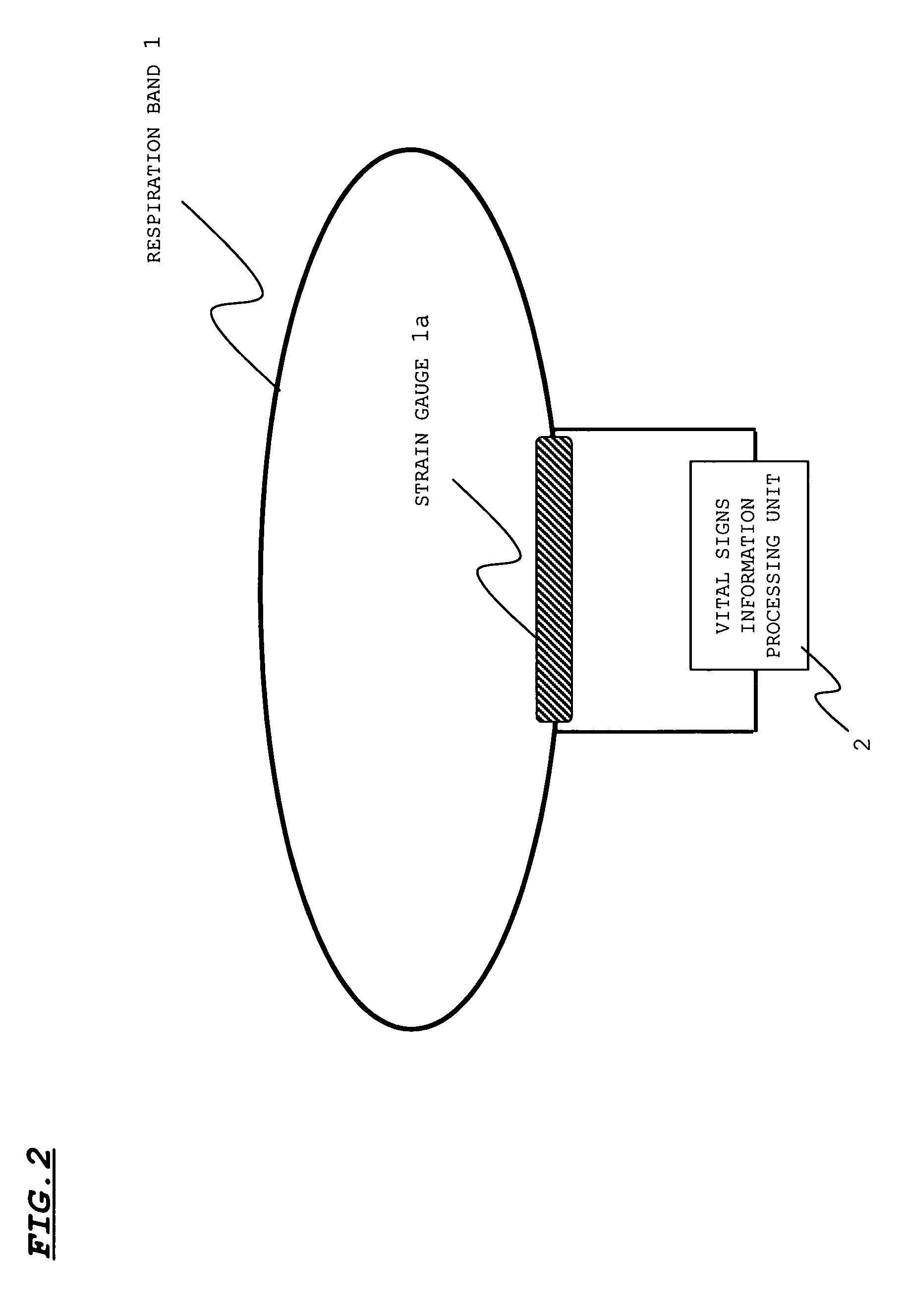
[0033]The respiratory band 1 is, as shown in FIG. 2, an elastic band having a strain gauge 1a (for example, an elastic rubber tube having conductive liquid included therein). The respiratory band 1 is wound around the chest or abdominal area of the subject, and respiratory movement of the subject expands and contracts t...


PUM


Abstract

A sleep state of a subject is estimated from respiration signals that are readily detected without restraining the subject. From a voltage waveform based on respiratory movement of a person, positive peak values and the (time) interval between adjacent peaks are calculated. Also obtained is the area of a region that is enclosed by the voltage waveform and a time axis between peaks, and the average value and dispersion value of the obtained inter-peak areas are calculated. The calculated values are used to set a preliminary sleep state value for a given period, and sleep state values over plural periods are factored in to estimate a sleep state at a given time point.

Description

[0001]This application claims priority under 35 U.S.C. §119 of Japanese Patent Application No. 2004-201155 filed Jul. 7, 2004.BACKGROUND OF THE INVENTION[0002]1. Field of the Invention[0003]The present invention relates to a sleep state estimating device which estimates a sleep state based on vital signs information, and to a program product for executing a sleep state estimation function.[0004]2. Description of the Related Art[0005]Recently heightened health consciousness among people has created a desire to manage their health by day-to-day sleep control in their household.[0006]During sleep, a person experiences various states through a night. The sleep is divided broadly into two types, namely, REM sleep and non-REM (NREM) sleep. The fact that the NREM sleep alternates with the REM sleep periodically several times during the sleep is known. In general, the sleep undergoes transition as follows. That is, a sleep state during the NREM sleep gradually transits from the light sleep ...

Claims


Application Information

Patent Timeline
Patent Type & Authority Patents(United States)
IPC IPC(8): A61B5/08
CPCA61B5/1135A61B5/4812A61B5/4809
Inventor OKADA, SHIMAFUJIWARA, YOSHIHISAYAMAMOTO, YASUSHIYONEDA, FUMIIKI
Owner SANYO ELECTRIC CO LTD
Why Eureka
Try Eureka