Keypad PCB assembly for mobile phone with light guide plate

a technology of printed circuit board and mobile phone, which is applied in the direction of telephone set construction, electrical apparatus, legends, etc., can solve the problems of shortening the life of the battery, inhomogeneity of light-emitting, and high cost driving circuit, so as to achieve high power consumption, high cost and noise occurren

Inactive Publication Date: 2008-09-30
KBF
View PDF14 Cites 13 Cited by
  • Summary
  • Abstract
  • Description
  • Claims
  • Application Information

AI Technical Summary

Benefits of technology

[0008]Accordingly, the present invention has been made to solve the above-mentioned problems occurring in the prior art, and the present invention provides a keypad printed circuit board (PCB) for a mobile phone integrated with a light guide plate and using a light emitting diode (LED) and a light guide plate while solving the problems of a conventional LED type structure, such as inhomogeneity in light emission and higher power consumption. The keypad PCB has advantages of an electroluminescence (EL)-type light emission structure, such as power saving, super thinning, and homogeneous light-emission features without adopting the EL type structure having defects of high costs and noise occurrence.

Problems solved by technology

Such an LED type has problems in that due to using so many LEDs, high power consumption is caused to shorten the lifetime of a battery, and in view of light-emitting, a difference in luminance occurs depending upon near-far effect from the LEDs, causing inhomogeneity in light-emitting.
However, the EL type has problems in that noises occur due to electrical interference, and it needs a high cost driving circuit, thereby increasing production costs.
Further, while there is an attempt to improve the quality of light-emitting by adapting a light guide plate for back light to a mobile phone, there is not yet proposed a practical method of manufacturing a light-emitting assembly to solve the above problems as well as to satisfy the objective light-emitting feature and easy productivity.

Method used


Image

  • Keypad PCB assembly for mobile phone with light guide plate
  • Keypad PCB assembly for mobile phone with light guide plate
  • Keypad PCB assembly for mobile phone with light guide plate

Examples


Embodiment Construction

[0015]Hereinafter, an exemplary embodiment of the present invention will be described with reference to the accompanying drawings. In the following description and drawings, the same reference numerals are used to designate the same or similar components, and so repetition of the description on the same or similar components will be omitted.

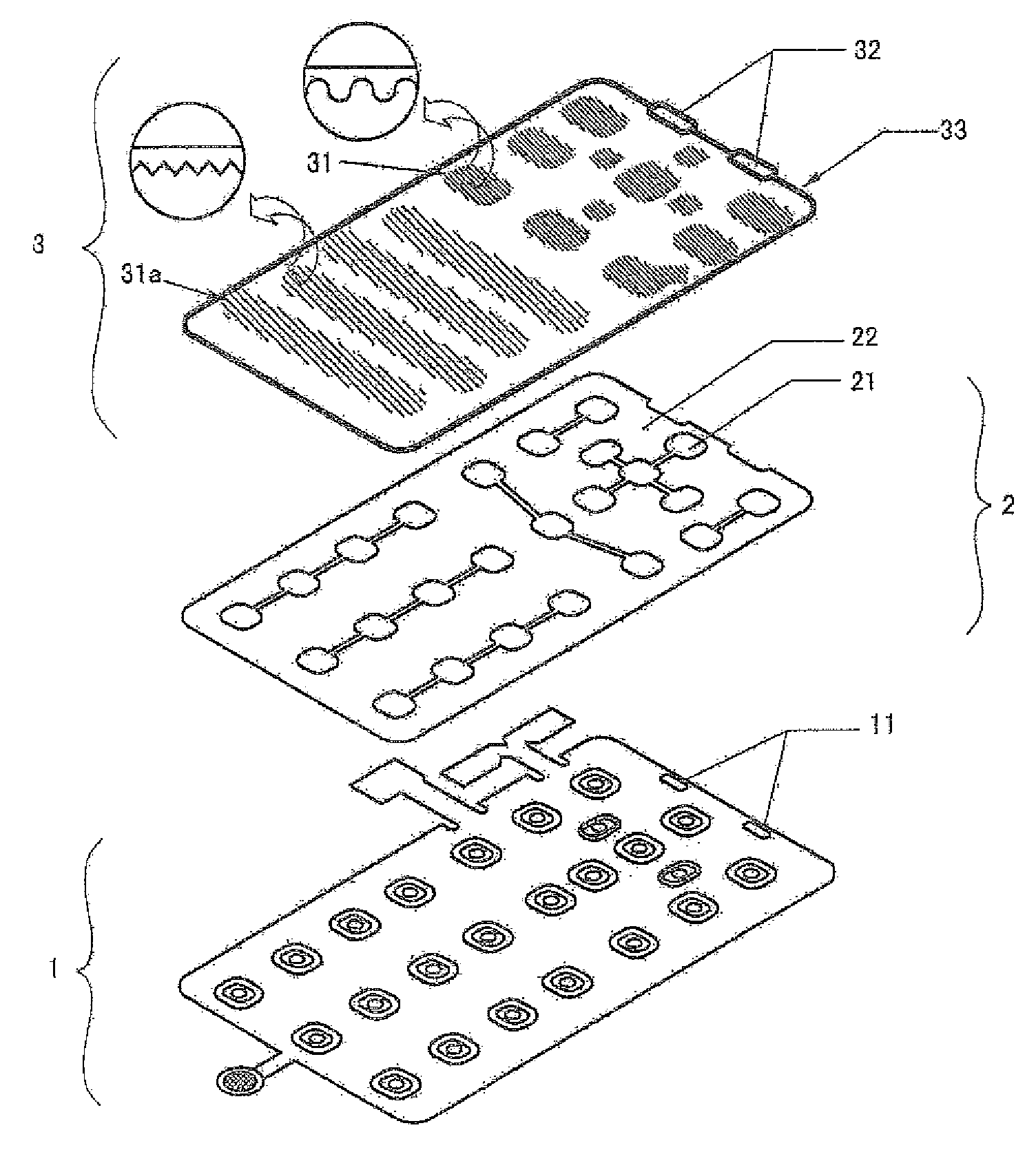
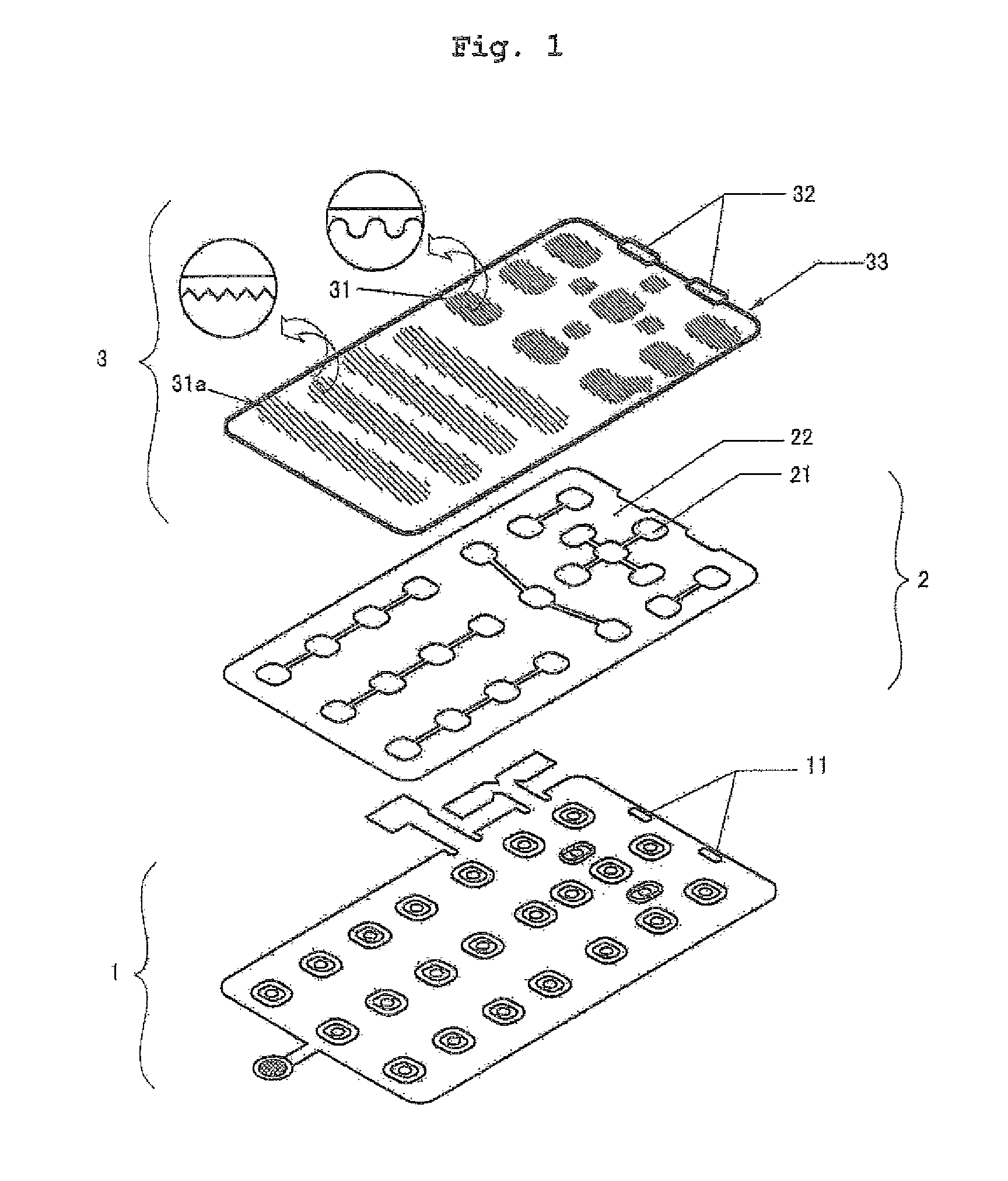
[0016]FIG. 1 is an exploded perspective view of a keypad light-emitting printed circuit board (PCB) assembly according to the present invention. The PCB assembly includes a printed circuit board (PCB), a metal dome section, and a light guide plate as named from the bottom.

[0017]The present invention relates to a keypad PCB for a mobile phone having a light-emission function. The elements other than light-emission function-related elements are the same as those of a conventional keypad for a mobile phone, so the detailed explanation thereof will be omitted.

[0018]As for the PCB 1, a PCB adopted to an electroluminescence (EL) keypad or a flexible pr...


PUM


Abstract

A keypad printed circuit board (PCB) assembly for a mobile phone integrated with a light guide plate providing a light-emitting function using a light emitting diode (LED) and the light guide plate is provided. The keypad PCB assembly includes a PCB on which a plurality of light emitting diodes (LEDs) is surface-mounted such that they are able to emit light from a side of the PCB, a metal dome section including metal dome parts attached to positions corresponding to signal contacts of the PCB, and a dome tape covering a gap between the metal dome parts excluding a portion overlapped with the LEDs, and a light guide plate coupled to an upper portion of the metal dome section so that the light guide plate and the metal dome section are integrated into one piece, leaving the space therebetween, and having thereunder an uneven pattern reflecting light incident from the LEDs, an LED cover provided on a position corresponding to the LEDs, and a circumferential light-shielding part filling the end-side space between the light guide plate and the metal dome section.

Description

BACKGROUND OF THE INVENTION[0001]1. Field of the Invention[0002]The present invention relates to a keypad printed circuit board (PCB) assembly for a mobile phone, and more particularly to a keypad PCB assembly for a mobile phone integrated with a light guide plate providing a light-emitting function using a light emitting diode (LED) and the light guide plate.[0003]2. Description of Prior Art[0004]As generally known in the art, a light-emitting device of a keypad for a mobile phone is mainly a light-emitting diode (LED) type, but recently, there has been a trend towards distributing an electroluminescence (EL) type in high-cost models.[0005]The LED type is a type in which LEDs are surface-mounted to many positions (e.g., 10 to 20 points) on a keypad to illuminate the whole of the keypad. Such an LED type has problems in that due to using so many LEDs, high power consumption is caused to shorten the lifetime of a battery, and in view of light-emitting, a difference in luminance occur...

Claims


Application Information

Patent Timeline
Patent Type & Authority Patents(United States)
IPC IPC(8): H01H9/18
CPCH01H13/83H04M1/23H04M1/22H01H2219/018H01H2219/044H01H2219/062H01H2219/064H01H2219/056H01H13/705H01H2219/036H01H2219/037
Inventor KIM, WOO-CHUN
Owner KBF
Why Eureka
Try Eureka