Frame synchronization method and system

a frame and synchronization technology, applied in the direction of synchronizing arrangement, transmission, electrical equipment, etc., can solve the problems of inability to provide rapid re-synchronization and inability to adapt to existing techniques

Inactive Publication Date: 2008-09-30
ULTRA ELECTRONICS CANADA DEFENCE
View PDF15 Cites 10 Cited by
  • Summary
  • Abstract
  • Description
  • Claims
  • Application Information

AI Technical Summary

Problems solved by technology

Also, existing techniques may be susceptible to a loss of synchronization, and are, furthermore, not well adapted to provide rapid re-synchronization.

Method used


Image

  • Frame synchronization method and system
  • Frame synchronization method and system
  • Frame synchronization method and system

Examples


Embodiment Construction

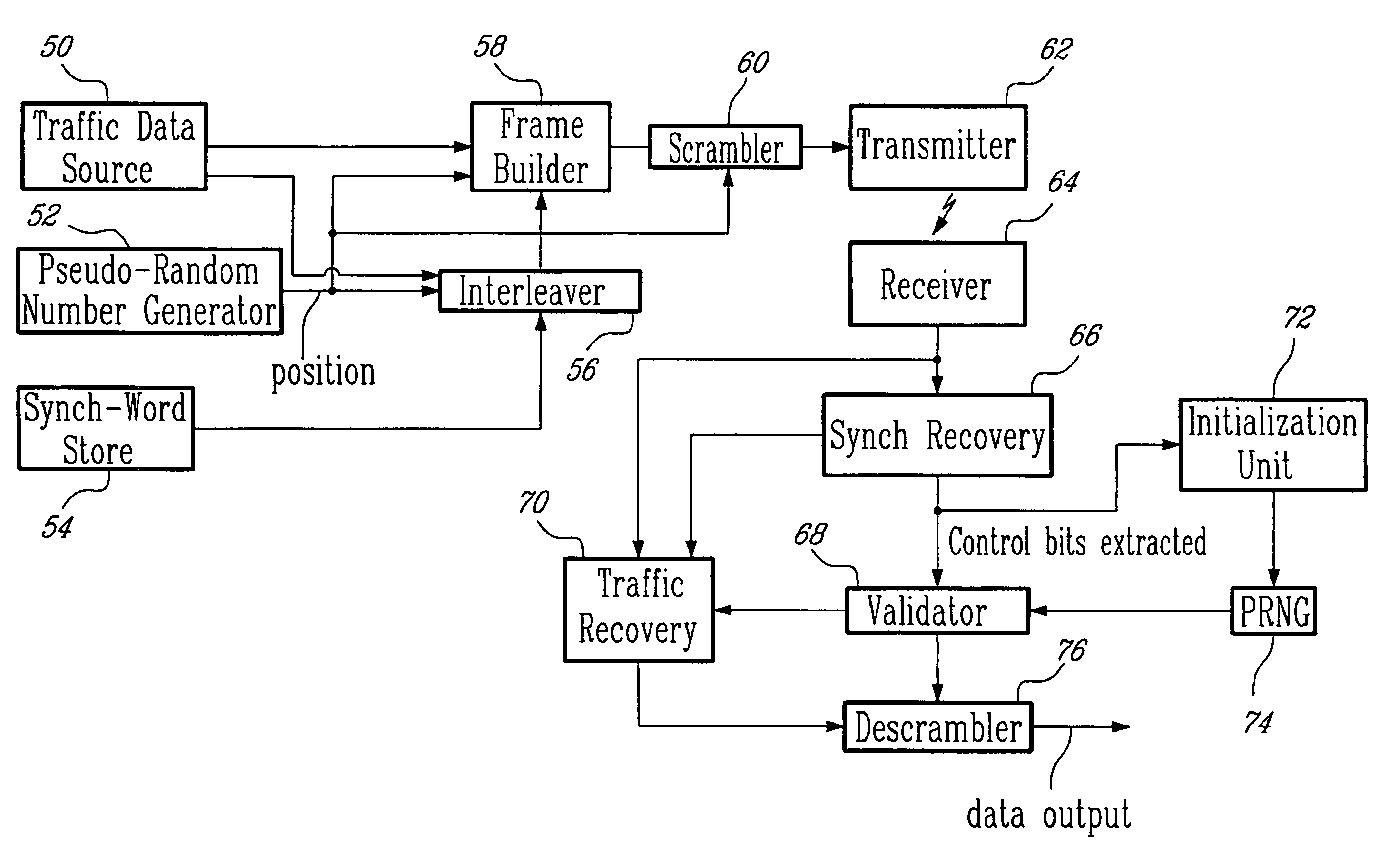
[0013]The present invention describes a frame synchronization technique that is used in digital data transmission. This technique involves the selection of a synchronization word that is suitable for good correlation in a receiver detector. Data or bits are interleaved within the synchronization word. These interleaved bits may be either traffic bits or control bits and they are interleaved within the synchronization word in a predetermined pattern, where this pattern is fixed for consecutive frames. Also, the interleaved traffic or control bits vary substantially between consecutive frames.

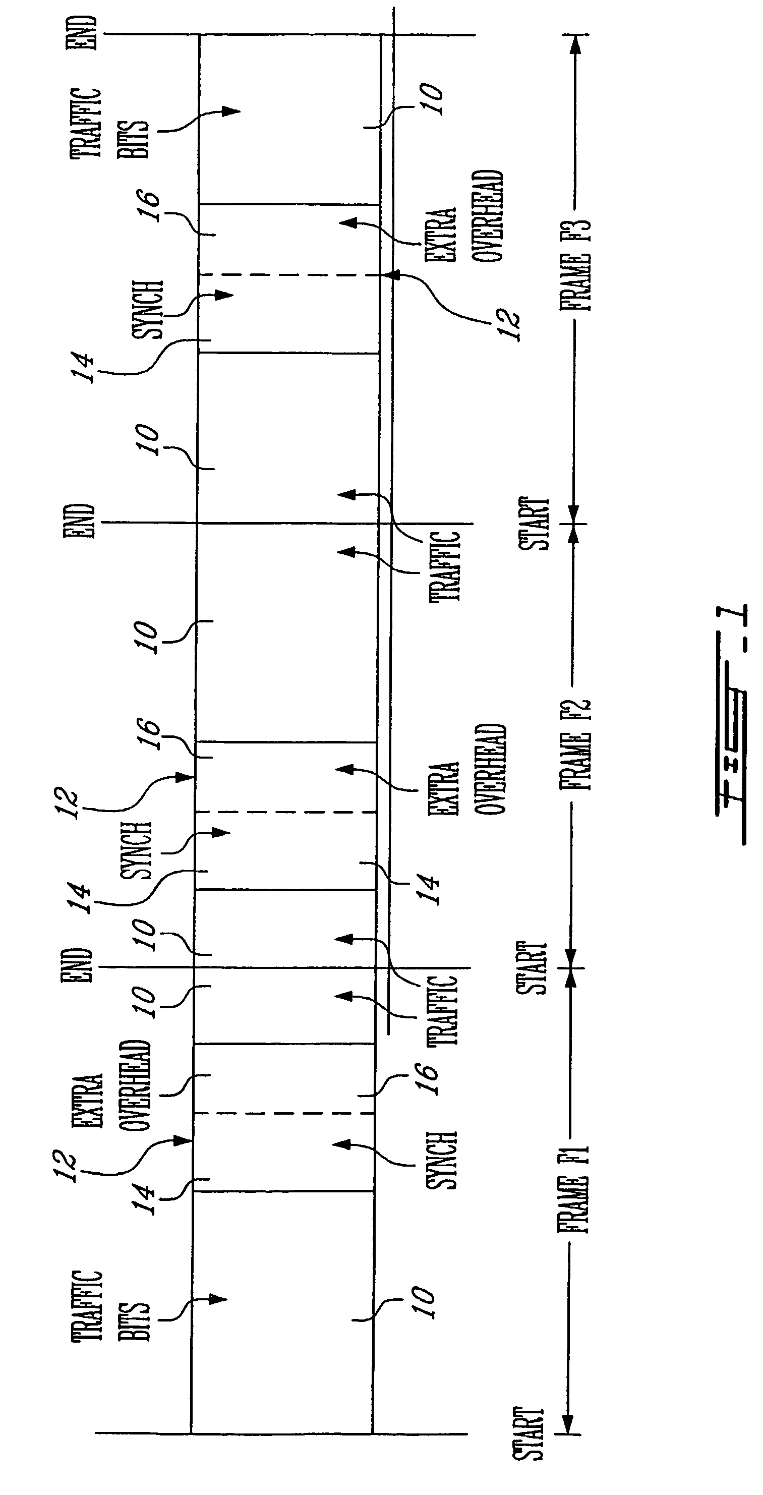
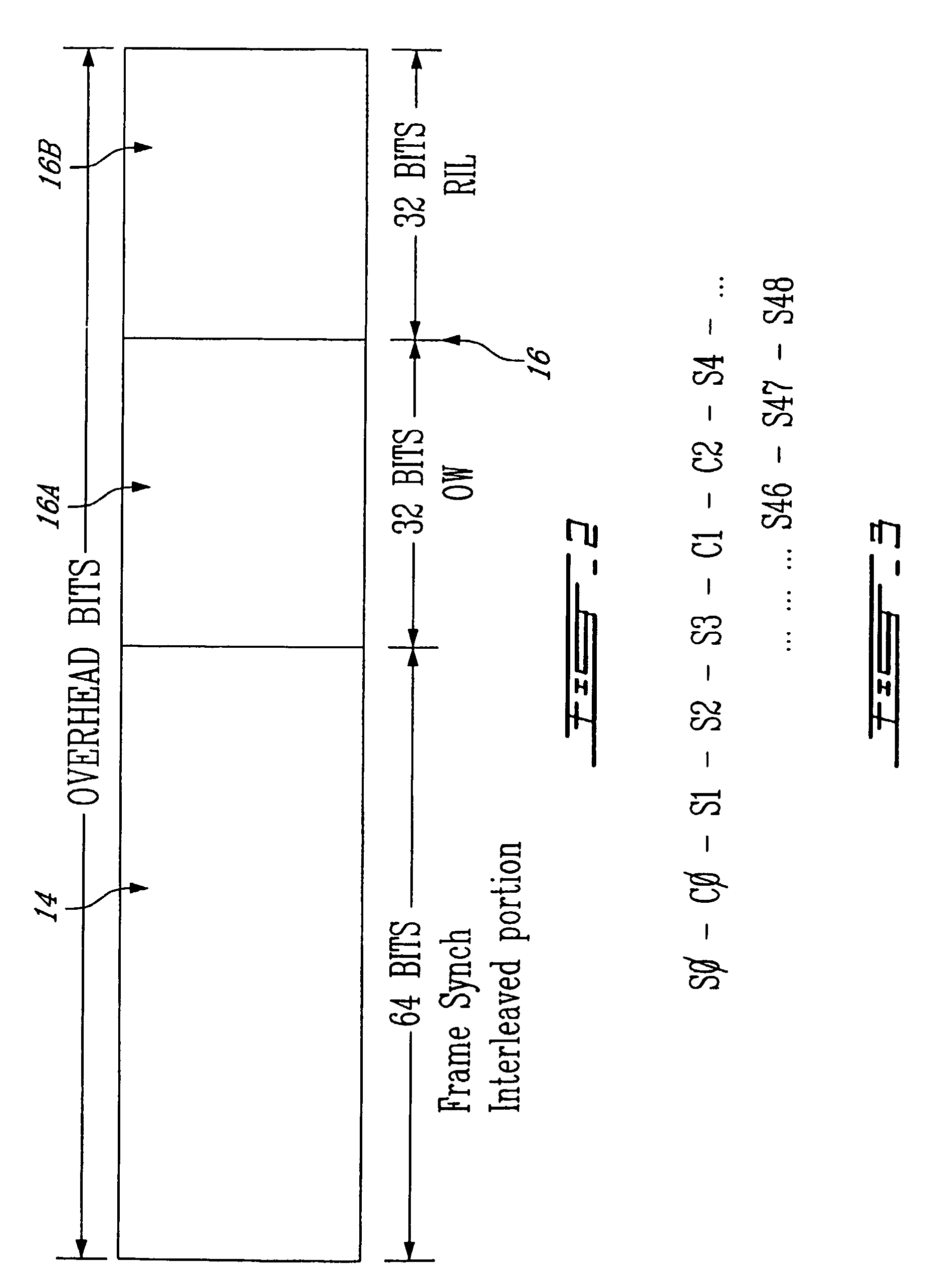
[0014]Reference is now made to FIG. 1 which illustrates a stream of digital data. More particularly, there is illustrated in FIG. 1 three frames F1, F2 and F3. Each frame is defined as a 2 msec time interval which contains the traffic bits, shown in FIG. 1 in separate traffic bit fields 10. Also depicted in FIG. 1 is a word of 128 adjacent overhead bits, located pseudo-randomly in the frame. This...


PUM


Abstract

A method and system for frame synchronization in a digital data transmission. A synchronization word is selected that is suitable for good correlation in a receiver detector. Either traffic bits or control bits are interleaved within the synchronization word in a predetermined pattern that is fixed for consecutive frames. The position of the sync word is varied from frame-to-frame. Also, the interleaved bits that are either traffic or control bits varies substantially between consecutive frames.

Description

BACKGROUND OF THE INVENTION[0001]The present invention relates to a method of frame synchronization in a digital data transmission. The present invention also relates to a frame synchronization system that embodies the method of this invention.[0002]In frame synchronization systems, particularly for critical applications, such as in military applications, it is becoming more important to use a scheme wherein the transmitted data (traffic) can not be easily deciphered or decoded by an eavesdropper. In this regard, a typical data transmission sequence is composed of consecutive frames of traffic data (bits) and an overhead word (bits). It is furthermore typical to provide, usually as part of the overhead word, a frame synchronization signal, usually of multiple bits disposed at the same position of each frame, usually at the start position of a frame. With such a fixed position synchronization word, there is not the level of security that one would like to see. Also, existing techniqu...

Claims


Application Information

Patent Timeline
Patent Type & Authority Patents(United States)
IPC IPC(8): H04L7/00H04J3/06H04L9/12
CPCH04J3/0605H04L9/0662H04L9/12
Inventor FORTE, MICHEL
Owner ULTRA ELECTRONICS CANADA DEFENCE
Why Eureka
Try Eureka