Ratcheting torque wrench

a torque wrench and torque technology, applied in the field of torque wrenches, can solve the problems of lengthen and achieve the effects of reducing friction and resulting wear, reducing the profile, and prolonging the useful life of the tool

Inactive Publication Date: 2008-10-07
GAUTHIER BIOMEDICAL
View PDF31 Cites 68 Cited by
  • Summary
  • Abstract
  • Description
  • Claims
  • Application Information

AI Technical Summary

Benefits of technology

[0012]According to a first aspect of the present invention, a driving tool includes a drive shaft disposed within a housing forming a handle for the tool. The drive shaft that is formed with an inner portion having an engaging ring disposed around the inner portion. The engaging ring including a number of engaging surfaces, such as slots, spaced around the periphery of the engaging ring. The inner portion of the drive shaft and the engaging ring are inserted within the handle housing such that the drive shaft is rotatable with respect to the handle. On opposite sides of the handle are disposed additional engaging surfaces or members that can contact the engaging surfaces on the engaging ring. The additional engaging surfaces can take various forms, such as plungers that hold a number of elongate pins therein that are selectively engageable with the engaging surfaces on the engaging ring. This provides the torque limiting mechanism with an opposed construction instead of an in-line construction to provide the handle incorporating the torque limiting mechanism with a low profile. However, the construction of the tool can also incorporate the torque limiting mechanism in an in-line construction, if desired. The engaging surfaces on the plungers are urged into engagement with the engaging surfaces on the engaging ring secured to the drive shaft by biasing members extending between the plungers and end caps affixed to opposed ends of the handle. The bias of the springs urges the plungers and engaging surfaces thereon into engagement with the slots to enable the engaging ring and the drive shaft to rotate in conjunction with the handle to drive the fastener into the substrate. However, should the torque transmitted through the drive shaft to the handle and plungers exceed the biasing force of the biasing members, the torque created by the rotation of the drive shaft will cause the drive shaft to push the engaging surfaces on the plungers past or out of engagement with the surfaces on the engaging ring, allowing the drive shaft to rotate independently of the handle. This mechanism greatly reduces the friction and resulting wear in the mechanism, lengthening the useful life of the tool.
[0013]According to still a further aspect of the present invention, the configuration of the engaging surfaces, e.g., depth of the slots on the engaging ring secured to the drive shaft, can be varied to increase or decrease the torque values that are provided by the mechanism for the tool without varying the biasing members utilized in the construction of the mechanism.
[0014]According to still another aspect of the present invention, the tool is additionally formed with a ratcheting mechanism that includes a central gear rotatably mounted within a recess formed in the outer portion of the drive shaft in a manner that prevents the gear from shifting axially or laterally with respect to the drive shaft. The gear is operably connected to the drive shaft opposite the inner portion and is located at least partially within the housing for the tool. The drive shaft supports the central gear, which defines a central opening, into which a shaft extender or other fastener-engaging device can be inserted, and has a number of teeth spaced around the periphery thereof. The shaft and the gear are maintained in position within the housing by a bearing positioned around the shaft adjacent the gear and engaged with the housing opposite the shaft. The bearing includes a smooth or otherwise essentially frictionless interior surface that is contacted by the shaft in order to enable the shaft to rotate freely with respect to the bearing. On the outer surface of the bearing, each bearing can include a sealing member that is engaged with the housing to both secure the bearing with regard to the housing, thereby preventing the bearing and the shaft positioned within the bearing from shifting with regard to the housing during the operation of the tool, and to seal the interior of the housing inwardly from the bearings. Thus, the gear which is attached to the shaft is prevented from shifting laterally or axially within the housing.
[0016]According to another aspect of the present invention, the ratcheting mechanism also includes a cap engageable with the bearing over the recess in which the mechanism is located that includes a central aperture aligned with the central opening in the gear. The cap includes a sealing member disposed along the periphery of the central aperture that sealingly engages the gear around the central opening in order to provide a fluid tight seal therebetween. The cap also engages a sealing surface disposed on the exterior of the housing around the recess on which another sealing member can be positioned in order to provide a fluid tight seal between the bearing and the cap. Therefore, when cleaning the tool after use or using the tool in environments where fluids are present, the fluids are prevented from penetrating past the bearing into the interior of the housing. As a result, no liquid, gas, debris or residual cleaning material is able to affect the normal operation of the mechanism.

Problems solved by technology

This mechanism greatly reduces the friction and resulting wear in the mechanism, lengthening the useful life of the tool.

Method used


Image

  • Ratcheting torque wrench
  • Ratcheting torque wrench
  • Ratcheting torque wrench

Examples


first embodiment

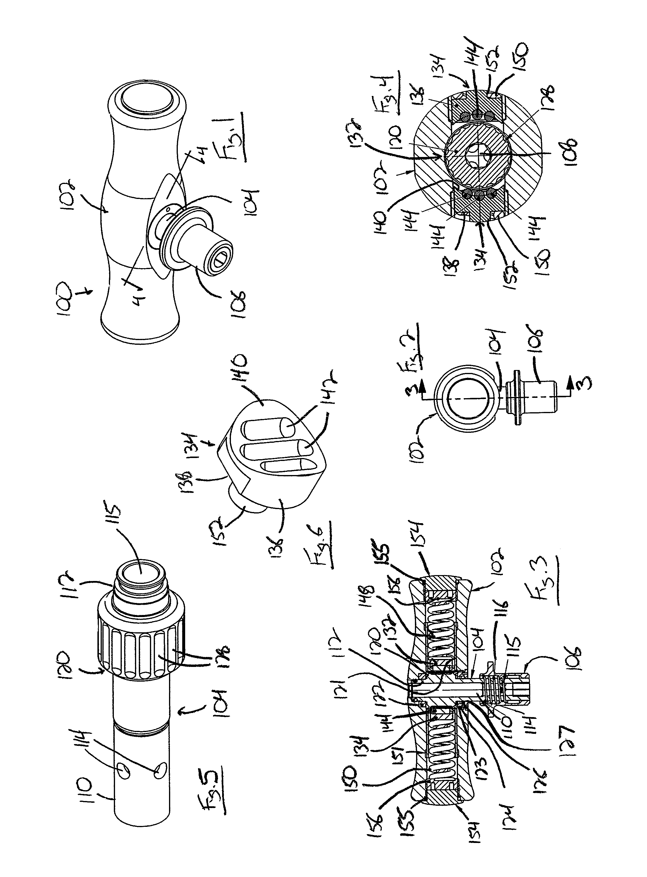
[0031]With reference now to the drawing figures in which like reference numerals designate like parts throughout the disclosure, a torque wrench constructed according to the present invention is indicated generally at 100 in FIG. 1. The wrench 100 includes a handle 102 from which extends a shaft 104 having a drive shaft release member 106 attached thereto opposite the handle 102. Release member 106 is utilized to secure a drive shaft 108 thereto in order to drive a fastener (not shown) that is engaged by the fastener-engaging shaft 108 into a substrate.

[0032]Looking now at FIGS. 3-5, the drive shaft 104 includes an outer section 110 integrally connected to an inner section 112 that is positioned within the handle 102. The outer section 110 is generally cylindrical in shape and includes a number of circular openings 114 spaced equidistant around the outer section 110. The openings 114 are adapted to receive ball bearings (not shown) therein that are used to engage and retain the fast...

second embodiment

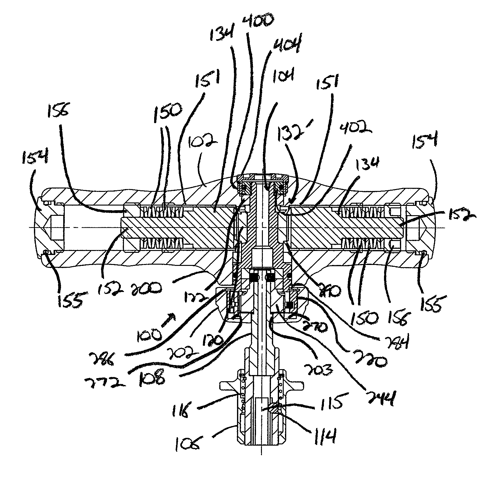
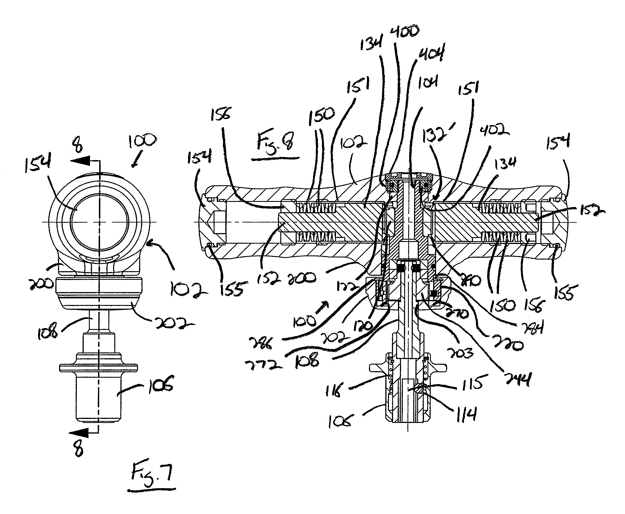
[0039]Referring now to FIGS. 7-9, the wrench 100 is illustrated. In this embodiment, the drive shaft 104 is offset from the center of the handle 102. Thus, the drive shaft 104 and fastener-engaging shaft 108 are positioned closer to one side of the handle 102, which allows the tool 100 to be utilized in locations where the previous embodiment of the tool 100 would be unworkable due to the length of the handle 102 extending from opposite sides of the drive shaft 104.

[0040]Further, as best shown in FIG. 8, due to the extended length of one side of the handle 102, the adjustment nut 156 is separated from the end cap 154 and disposed entirely within the channel 121 to vary the compression of the springs 150, thereby controlling the maximum torque level at which the mechanism 132 can be operated. In a preferred embodiment, the adjustment nut 156 is threadedly engaged with the interior of the channel 121 such that the nut 156 can be advanced or retracted within the channel 121 to the desi...

third embodiment

[0055]Referring now to FIG. 10, the torque limiting mechanism 300 for use within the tool 100 is illustrated. In the mechanism 300, the shaft 104 is integrally formed with a central section 302 having a generally square-cross sectional area adjacent the inner section 112 of the drive shaft 104. A frictional cam member 304 is formed with a generally square-cross section aperture 306 extending through the center thereof that is positionable around the central section 302 on the drive shaft 104 to secure the cam member 304 to the drive shaft 104. The cam member 304 has an exterior surface 308 with a number engaging surfaces 310 formed thereon that, in a preferred embodiment, is formed as a hexagonal surface 312. The hexagonal surface 312 forms a number of flat friction panels 314 spaced equidistant around the surface 312. The surfaces 314 on opposite sides of the cam member 304 are engaged by plungers 316 having generally flat engaging surfaces 318 that are pressed against the friction...


PUM


Abstract

A tool is provided for driving fasteners that includes a torque limiting mechanism therein. The torque limiting mechanism includes a first frictional engagement member disposed on the drive shaft for the tool that is engaged by one or more second frictional engagement members disposed on one or more sides of the first frictional member. The second frictional engagement members are biased into engagement with the first member by biasing members disposed within the handle that can be adjusted in order to provide more or less of a biasing force to control the frictional engagement of the second member with the first member and thereby control the torque limiting function of the torque limiting mechanism. In addition, a drive shaft is also engaged with a ratcheting mechanism that enables the tool to drive a fastener into a suitable substrate in only a single direction.

Description

CROSS-REFERENCE TO RELATED APPLICATIONS[0001]This application claims priority as a continuation-in-part application from U.S. patent application Ser. No. 11 / 645,942, filed Dec. 27, 2006, which is a continuation of U.S. patent application Ser. No. 11 / 232,634, filed Sep. 22, 2005, now U.S. Pat. No. 7,156,216, which is a continuation of U.S. patent application Ser. No. 10 / 969,402, filed on Oct. 20, 2004, now U.S. Pat. No. 6,948,605, which is a continuation of U.S. patent application Ser. No. 10 / 342,707, filed on Jan. 15, 2003, now U.S. Pat. No. 6,817,458, which claims priority from U.S. Provisional Patent Application Ser. No. 60 / 348,516, filed on Jan. 16, 2002, as well as from U.S. Provisional Patent Application Ser. No. 60 / 802,747, filed on May 23, 2006.FIELD OF THE INVENTION[0002]The present invention relates to torque wrenches, and, more specifically, to a torque wrench including both a torque limiting mechanism and a ratcheting mechanism disposed within the handle of the wrench.BAC...

Claims


Application Information

Patent Timeline
Patent Type & Authority Patents(United States)
IPC IPC(8): B25B23/14B25B13/46B25B23/143F16D41/12
CPCB25B13/463B25B15/04B25B23/1427F16D41/084F16D41/12F16D41/16
Inventor GAUTHIER, MICHAEL T.LANDOWSKI, STEVEN S.
Owner GAUTHIER BIOMEDICAL
Why Eureka
Try Eureka