Supercharge Your Innovation With Domain-Expert AI Agents!

Loader work machine

a work machine and loader technology, applied in the field of loaders, can solve problems such as difficulty in securing dimensional accuracy, and achieve the effect of improving productivity and easily securing the required dimensional accuracy

Active Publication Date: 2008-10-07
KUBOTA CORP
View PDF7 Cites 1 Cited by
  • Summary
  • Abstract
  • Description
  • Claims
  • Application Information

AI Technical Summary

Benefits of technology

[0006]Having regard to the prior art noted above, the object of the invention is to decrease the number of welded parts and weld lengths, thereby improving productivity and easily securing required dimensional accuracy.
[0016]By forming the main frame as a one-piece plate, the number of welded parts and the weld lengths may be decreased, thereby achieving improved productivity and reduced cost, and securing required dimensional accuracy with ease.
[0018]In one preferred embodiment of the invention, said support base is formed cylindrical, said main frame has a mounting bore fitted and welded to said support base, said mounting bore, said engageable member and said connectable member being formed of cast steel to be integral with said main frame. With this construction, the same main frame and / or support base may be used on both right and left sides of the vehicle body, which contributes a further cost reduction.
[0019]In another preferred embodiment, said mounting plate extends forwardly of said vehicle body from a mounting position on said support base, and is bent transversely inwardly at an intermediate position thereof. This construction increases a steering angle of each front wheel.

Problems solved by technology

The above conventional loader work machine has room for improvement with regard to low productivity, since each main frame is formed of many welded parts with large weld lengths, and to difficulty in securing dimensional accuracy owing to welding distortions.

Method used


Image

  • Loader work machine
  • Loader work machine
  • Loader work machine

Examples


Embodiment Construction

[0026]A preferred embodiment of the invention will be described hereinafter with reference to the drawings.

[0027]In the following description, the terms “fore and aft direction” and “right and left direction” are defined as forward, rearward, rightward and leftward directions with reference to an advancing direction of a working vehicle, and “vertical direction” is vertical with respect to a vehicle body.

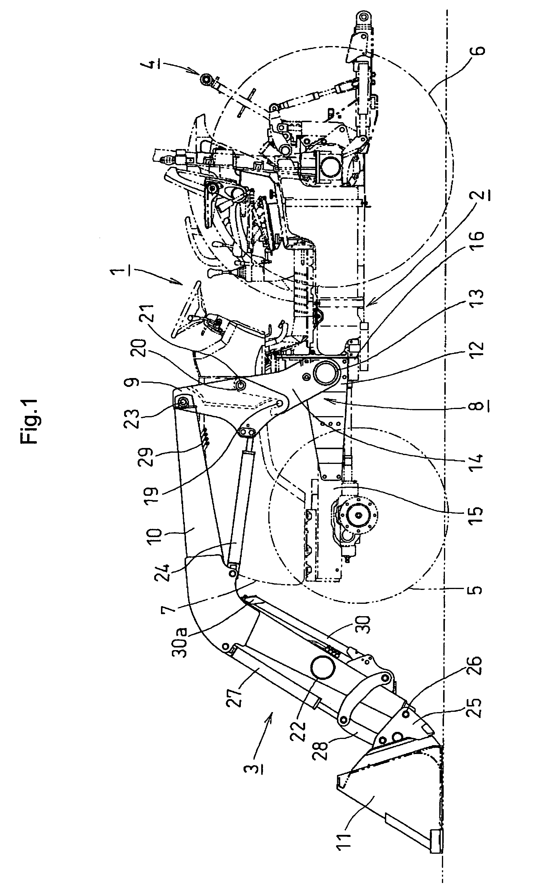
[0028]FIG. 1 shows a tractor-mounted loader work machine 1 as one example of a working vehicle (load handling vehicle). The loader work machine 1 includes a tractor (vehicle body) 2 having a front loader (working implement) 3 attached to a front portion thereof, and a three-point link mechanism 4 attached to a rear portion thereof for connecting a further, rear working implement such as a cultivator.

[0029]The tractor 2 is of a two-axle and four-wheel type with a pair of right and left front wheels 5 and a pair of right and left rear wheels 6, and has a hood 7 disposed at the front p...


PUM


Abstract

A loader work machine including a vehicle body, and a working implement having booms and boom cylinders and mounting frame units for attaching the working implement to a front portion of the vehicle body. Each of the mounting frame units includes a mounting plate fixed to the vehicle body, a support base projecting laterally outward from the mounting plate, a main frame erected on the support base, and a side frame for pivotally supporting proximal ends of one of the booms and one of the boom cylinders. The side frame includes right and left side plates and a connecting element for interconnecting the right and left side plates. The side frame is detachably attached to the main frame by engaging an engaging member disposed in a lower portion of the side frame with an engageable member of the main frame, and connecting a connecting member formed on the side frame to a connectable member formed on the main frame. The main frame is formed as a one-piece plate insertable between the right and left side plates.

Description

BACKGROUND OF THE INVENTION[0001]1. Field of the Invention[0002]This invention relates to a loader work machine having a working implement such as a front loader attached to a front portion of a vehicle body such as a tractor.[0003]2. Description of the Related Art[0004]In some conventional loader work machines, side frames disposed on opposed lateral sides of the vehicle body for supporting booms are detachably attached to respective mounting frames on the lateral sides by fitting engaging pins into respective recesses of receiving members and inserting mounting pins through respective bosses on the lateral sides. In such a conventional loader work machine, each of the mounting frames includes a mounting plate to the vehicle body, a support base projecting laterally outwardly from the mounting plate and a main frame fixed to a laterally outward end of the support base. Each main frame is formed to have a box shape by welding a plurality of metal plate members (see JP-A-2001-132006 ...

Claims


Application Information

Patent Timeline
Patent Type & Authority Patents(United States)
IPC IPC(8): B66C23/00
CPCE02F3/34E02F3/627
Inventor NISHI, RYOICHIYAMAGUCHI, SHUSAKUISHIDA, ARINOBUOYAMA, KOSUKE
Owner KUBOTA CORP
Features
  • R&D
  • Intellectual Property
  • Life Sciences
  • Materials
  • Tech Scout
  • Unparalleled Data Quality
  • Higher Quality Content
  • 60% Fewer Hallucinations
Learn More