
Golf ball

a golf ball and mold technology, applied in the field of molds for golf balls, can solve the problems of golf ball cover dimple pattern formation, mold flash, and other projecting surface imperfections, and achieve the effect of minimizing mold flash

Active Publication Date: 2008-10-07
ACUSHNET CO
View PDF21 Cites 24 Cited by
  • Summary
  • Abstract
  • Description
  • Claims
  • Application Information

AI Technical Summary

Benefits of technology

The solution achieves improved aerodynamic symmetry, increased dimple coverage, reduced flash, and minimized effort in flash removal, resulting in a golf ball with enhanced flight consistency and cosmetic appeal.

Problems solved by technology

In addition, the cover blanks are simultaneously molded into conformity with the interior configuration of the hemispherical molds which results in the formation of the dimple pattern on the periphery of the golf ball cover.
As in all molding operations, when the golf ball is removed from the hemispherical molds subsequent to the molding operation, it will have molding flash, and possibly other projecting surface imperfections thereon.
However, this practice increases the amount of un-dimpled surface on the ball, which can result in reduced ball flight distance.
While this could potentially improve compliance with the symmetry, they did not sufficiently improve dimple coverage, since the parting lines include straight segments that do not permit tight dimple packing on opposite sides of the equator.
A stepped path often results in a greater loss of dimple coverage than a straight path because it discourages interdigitation for a larger number of dimples.

Method used


Image

  • Golf ball
  • Golf ball
  • Golf ball

Examples


Embodiment Construction

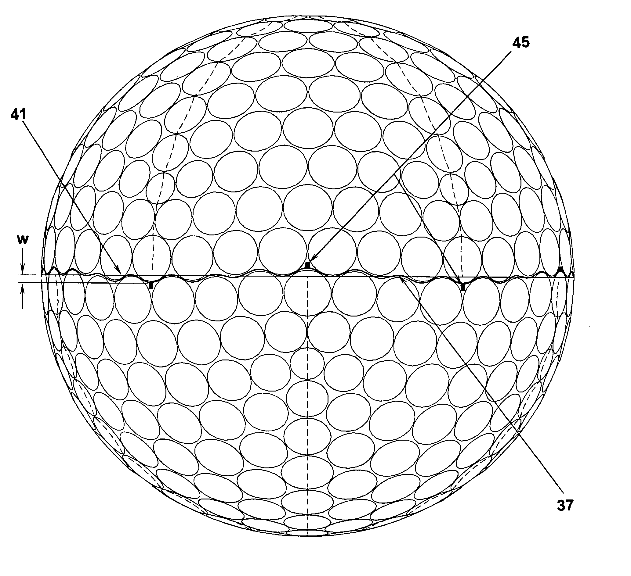
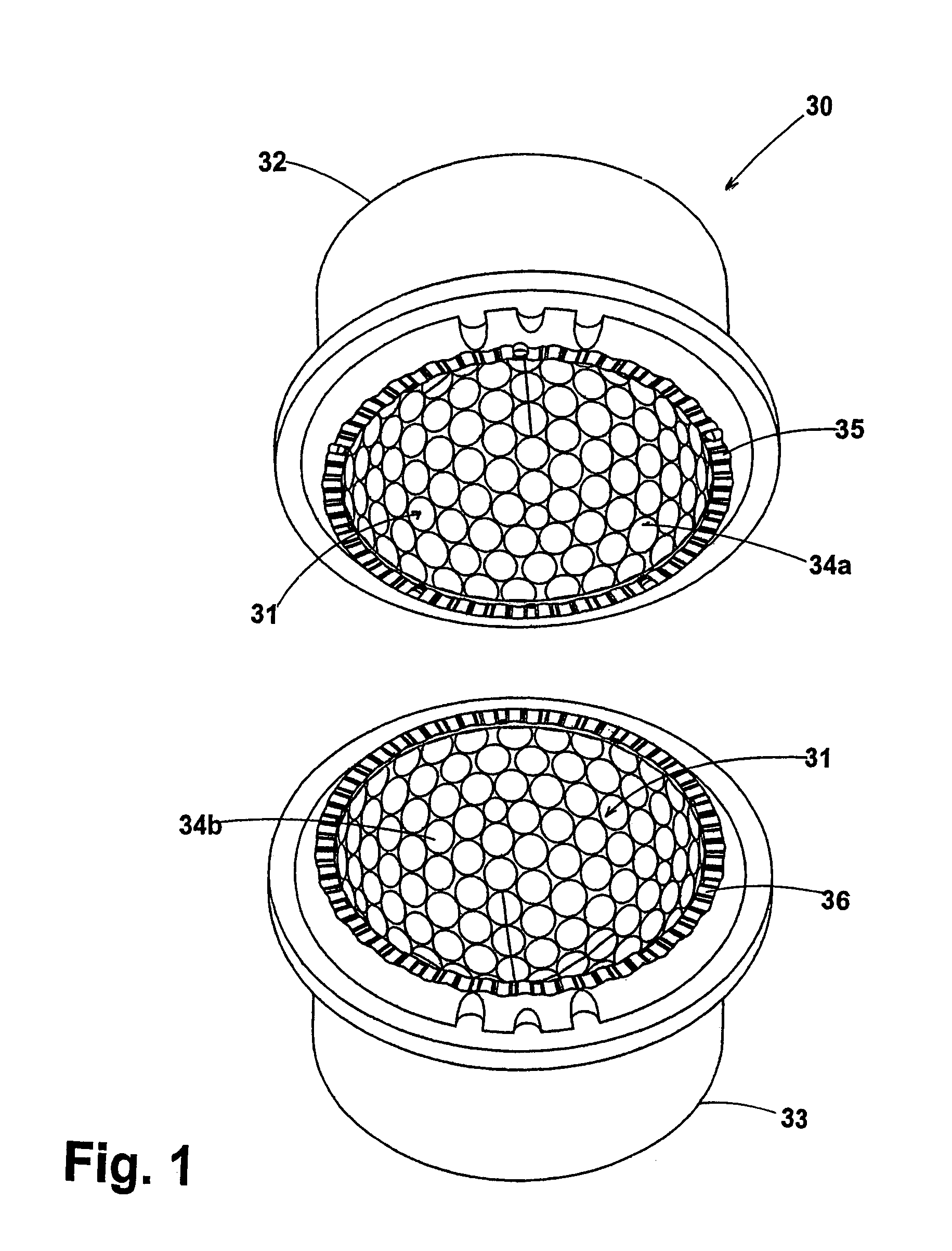
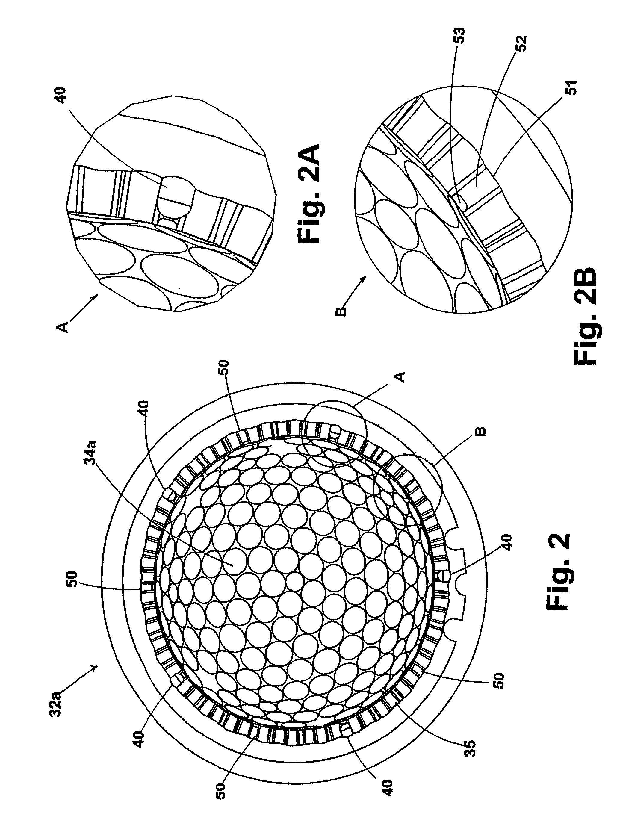
[0024]Referring to FIGS. 1 to 2b, wherein an improved mold of the present invention is shown, with the mold being indicated by the reference numeral 30, the mold 30 having a spherical cavity 31 which is used to form a cover for a golf ball wherein the mold 30 comprises generally hemispherical mold halves, an upper mold half 32 and a lower mold half 33, both halves having interior dimple cavity details 34a and 34b respectively with the details of the upper mold half 34a shown in FIGS. 2, 2A and 2B, for a mold designed to form a castable cover over a core, and when these halves are mated they define a dimple arrangement therein. Any dimple arrangement, such as icosahedral, octahedral, cube-octahedral, dipyramid, and the like could have the dimple pattern, although the preferred dimple pattern for the preferred embodiment of the invention is the icosahedron pattern. Although the preferred dimple is circular when viewed normal to the spherical cavity surface, the dimples may be oval, tr...


PUM

PropertyMeasurementUnit
lengthaaaaaaaaaa
wavelengthaaaaaaaaaa
lengthaaaaaaaaaa

Abstract

A golf ball that is formed by a mold developed from a computerized modeling system such as CAD or CAE in combination with a CNC machine tool which superimposes a short waveform, or multiple waveforms, onto a longer base waveform to create a non-planar parting line that is functionally dependent on the underlying dimple geometry. The non-planar parting line is comprised of a plurality of peaks and valleys that are offset from the dimple perimeters, as not to bisect any dimple edge. Also, dimples on one side of the parting line interdigitate with dimples on the other side to form a more uniform distribution of dimples over the entire golf ball surface. Still further, the non-planar parting line has a amplitude which is less than 0.02 inch from an axis substantially coincident with the equator of the ball and the length of the parting line is less than 110 percent of the length of a curve defined by the circumference of the equator. Located at a plurality of sites on the non-planar parting line and offset from the equator are tabs which are formed on the ball to aid in the finishing operation wherein flash is removed from the ball parting line. The tabs are created by true sprues (vents) and false sprues on the parting surfaces of the ball mold halves.

Description

CROSS-REFERENCE TO RELATED APPLICATIONS[0001]The present invention is a continuation-in-part of a co-pending U.S. application Ser. No. 11 / 273,175, filed on Nov. 14, 2005, which was a continuation of U.S. application Ser. No. 10 / 797,796, filed on Mar. 10, 2004. The disclosures of which are incorporated herein in their entirety.FIELD OF THE INVENTION[0002]The invention relates in general to a mold for forming a golf ball, and more particularly, to an improved golf ball having a non-planar parting line based on a superposition of waveforms which are functionally dependent on the dimple pattern of the ball.BACKGROUND OF THE INVENTION[0003]The usual golf ball manufacturing techniques include several different steps, depending on the type of ball, such as one, two, three or even more than three piece balls. According to the traditional method, a solid or composite elastomeric core is made, and an outer dimpled cover is formed around the core.[0004]The two standard methods for molding a co...

Claims


Application Information

Patent Timeline
Patent Type & Authority Patents(United States)
IPC IPC(8): A63B37/12H04J1/00
CPCA63B37/0004A63B45/00B29C33/005B29C43/003B29C43/027B29C45/0025A63B37/0006B29C33/303B29C2045/0034B29L2031/54B29L2031/545A63B37/00065
Inventor NARDACCI, NICHOLAS M.AOYAMA, STEVENWILSON, ROBERT A.
Owner ACUSHNET CO
Learn More