Expandable interbody fusion cage

a fusion cage and expandable technology, applied in bone implants, medical science, prostheses, etc., can solve the problems of neglecting the need to restore the curvature affecting the normal anatomy of the fused spinal segment, and general acceptance of over-reaming of the posterior portion. , to achieve the effect of restoring lordosis, facilitating insertion and large siz

Inactive Publication Date: 2008-10-07
SOFAMOR
View PDF87 Cites 254 Cited by
  • Summary
  • Abstract
  • Description
  • Claims
  • Application Information

AI Technical Summary

Benefits of technology

[0015]Still another object of the present invention is to provide an expandable intervertebral device configured for easy insertion and expandable to a larger size to establish lordosis.
[0016]Yet a further object of the present invention is to provide an improved method for inserting an expandable intervertebral device into a disc space to restore lordosis.

Problems solved by technology

One problem that is not addressed by the above prior devices concerns maintaining and restoring the normal anatomy of the fused spinal segment.
With the prior devices, the need to restore this curvature is neglected.
However, this over-reaming of the posterior portion is generally not well accepted because of the removal of load bearing bone of the vertebrae and because it is typically difficult to ream through the posterior portion of the lower lumbar segment where the lordosis is the greatest.
In most cases using implants of this type, no effort is made to restore the lordotic curvature so that the cylindrical implant is likely to cause a kyphotic deformity as the vertebrae settles around the implant.
This phenomena can often lead to revision surgeries because the spine becomes imbalanced.
However, these devices require an opening at least as large as the largest segment of the device.
The requirement for such a relatively large opening may limit the use of such devices, particularly where access to the spine is limited due to obstructing vessels and neurological structures.
However, these implants do not allow the device to be easily and securely inserted into a disc space and the internal expansion mechanism limits the ability to pack the interior with a large amount of bone in-growth material.

Method used


Image

  • Expandable interbody fusion cage
  • Expandable interbody fusion cage
  • Expandable interbody fusion cage

Examples


Embodiment Construction

[0035]For the purposes of promoting an understanding of the principles of the invention, reference will now be made to the embodiments illustrated in the drawings and specific language will be used to describe the same. It will nevertheless be understood that no limitation of the scope of the invention is thereby intended, such alterations and further modifications in the illustrated devices, and such further applications of the principles of the invention as illustrated therein being contemplated as would normally occur to one skilled in the art to which the invention relates.

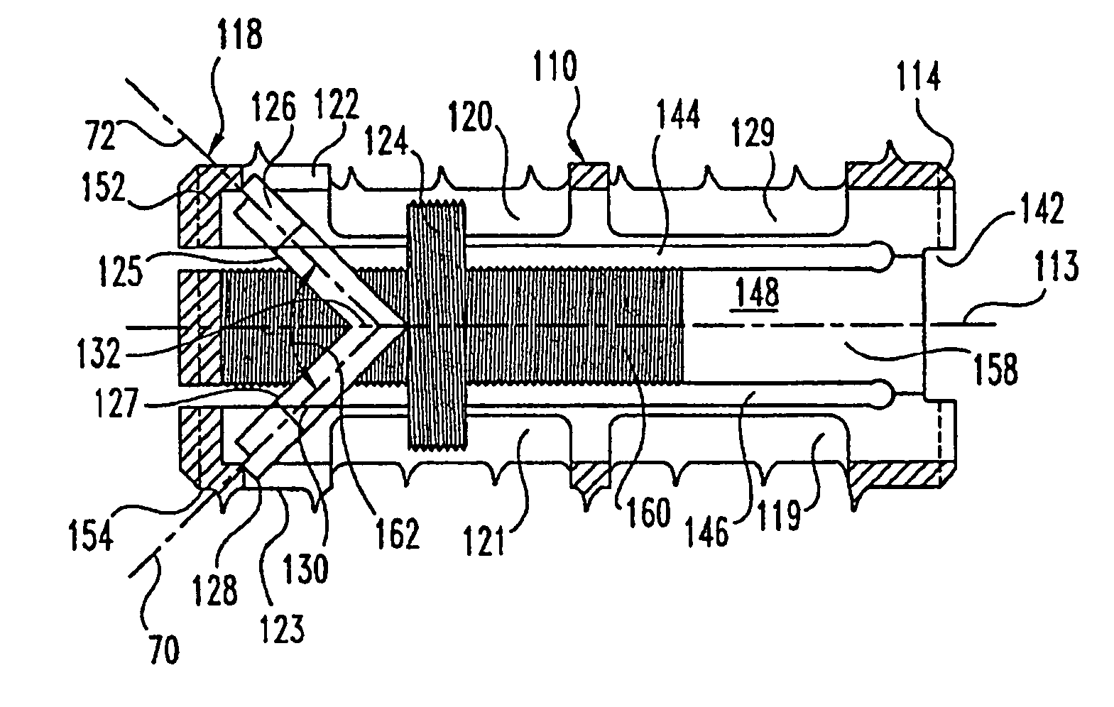
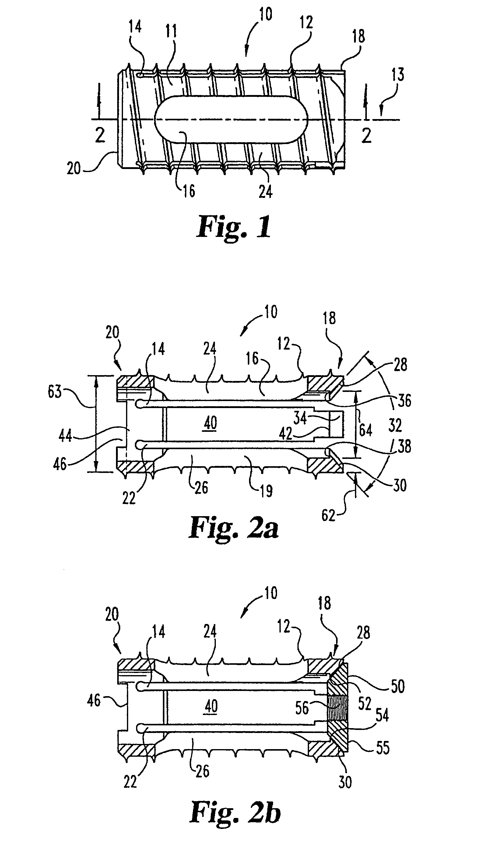
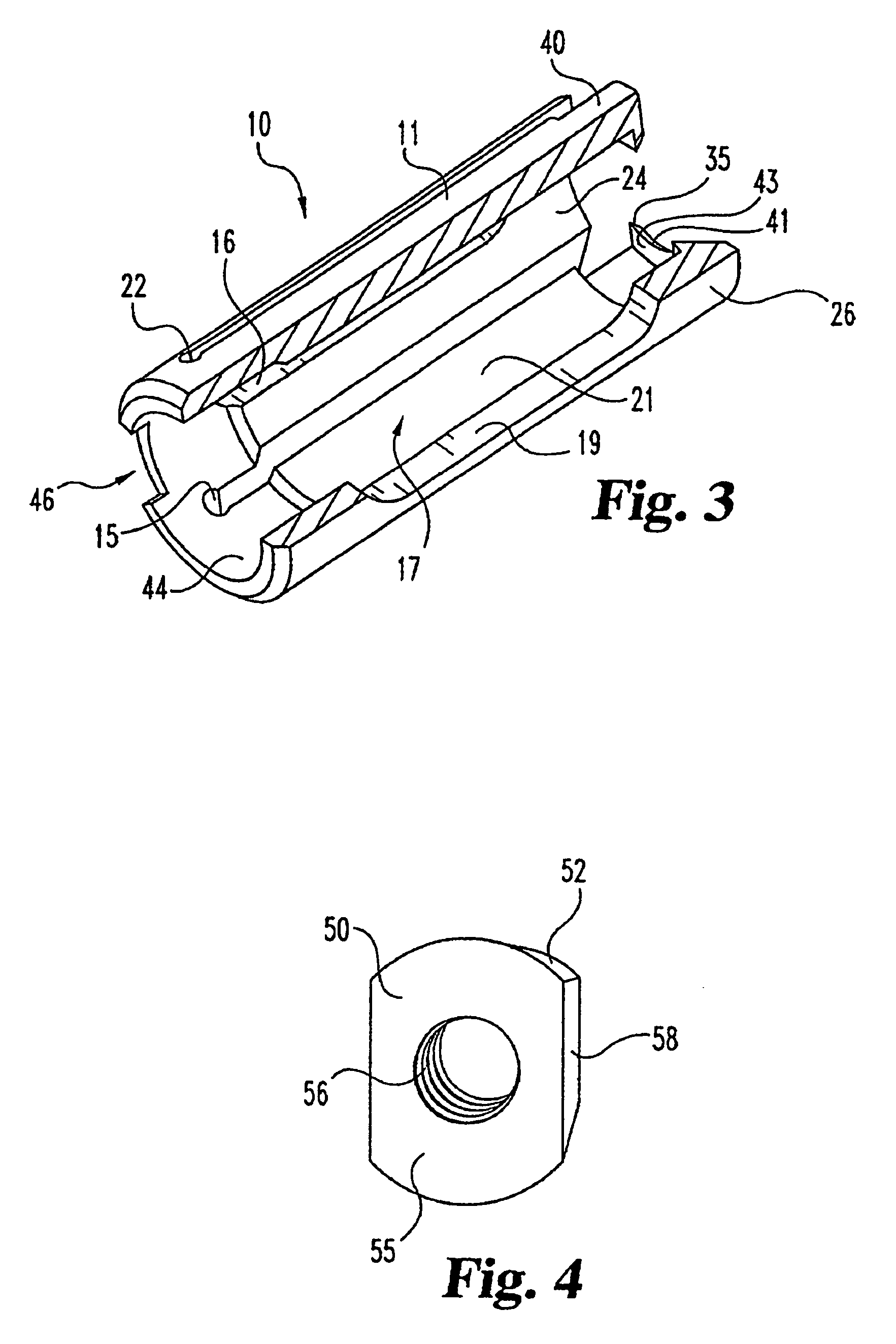
[0036]Referring now to FIGS. 1 through 3, there is shown a first embodiment of an expandable cage 10 in accordance with the present invention. In this embodiment of the invention, expandable cage 10 has a cylindrical outer surface 11 defining an external thread pattern 12 (not shown in FIG. 3) adapted to engage two adjacent vertebra (see FIGS. 7a and 7b) and to advance the cage into the disk space as cage 10 i...


PUM


Abstract

An expandable intervertebral device including a body extending generally along a longitudinal axis and including at least two branch portions coupled together adjacent an end portion of the body. The device further includes an expansion member positioned between the at least two branch portions with at least a portion of the expansion member arranged at an angular orientation relative to the longitudinal axis whereby a change in the angular orientation relative to the longitudinal axis urges the at least two branch portions apart to expand the body.

Description

CROSS REFERENCE TO RELATED APPLICATIONS[0001]The present application is a continuation of U.S. application Ser. No. 09 / 949,516, filed Sep. 7, 2001, now abandoned, which is a continuation of U.S. application Ser. No. 09 / 763,073, filed May 16, 2001 and issued as U.S. Pat. No. 6,436,140, which claims foreign priority benefits of International Patent Application Number PCT / 1B99 / 01478, filed Aug. 26, 1999, and French Patent Application Number FR98 / 10832, filed on Aug. 28, 1998, the contents of each application hereby being incorporated by reference.BACKGROUND OF THE INVENTION[0002]The present invention relates to an implantable device for promoting fusion between two adjacent bony structures and a method of inserting the same. More particularly, the invention relates to an expandable fusion cage that may be inserted, in a reduced size configuration, into an intervertebral space and expanded after insertion to provide a desired size. While the device according to the present invention may...

Claims


Application Information

Patent Timeline
Patent Type & Authority Patents(United States)
IPC IPC(8): A61F2/44A61F2/00A61F2/02A61F2/28A61F2/30A61F2/46
CPCA61F2/446A61F2/4611A61F2/30744A61F2/442A61F2002/2817A61F2002/2835A61F2002/30143A61F2002/302A61F2002/30235A61F2002/30332A61F2002/30405A61F2002/30408A61F2002/30538A61F2002/30579A61F2002/30596A61F2002/30772A61F2002/30774A61F2002/30777A61F2002/30785A61F2002/30787A61F2002/3085A61F2002/4475A61F2002/4623A61F2002/4627A61F2002/4638A61F2220/0025A61F2220/0033A61F2230/0017A61F2230/0065A61F2230/0069A61F2250/0006A61F2/4603A61F2002/30593A61F2002/30594
Inventor LIU, MINGYANJOSSE, LOIC
Owner SOFAMOR
Why Eureka
Try Eureka