Snap-in connector for electrical junction box

a technology of electrical junction boxes and pin connectors, which is applied in the direction of coupling device connections, insulating bodies, manufacturing tools, etc., can solve the problems of poor pull-out strength, tangs or fingers not sitting properly, and the test results of commercially available cable connectors that do not meet one or more of the desired requirements, so as to improve the gripping of cable tabs, improve electrical contact, and maximize the engagement of tabs

Inactive Publication Date: 2008-10-07
HALEXSCOTT FETZER
View PDF33 Cites 37 Cited by
  • Summary
  • Abstract
  • Description
  • Claims
  • Application Information

AI Technical Summary

Benefits of technology

[0007]A more particular object of the invention is to provide a snap-in electrical connector for helical metal cable and conduit characterized by improved cable gripping tabs that are designed to maximize engagement of the tabs in the helical cable / conduit groove, thereby providing improved electrical contact and higher and more consistent pull-out strength than prior art designs.

Problems solved by technology

Tests conducted on commercially available cable connectors as described above have not met one or more of the desired requirements.
This is due in large part to the fact that the cable tangs or fingers do not seat properly in the helical grooves of the cable / conduit.
The failure of the tangs to seat in the helical grooves results in poor pull-out strength and poor electrical contact so that the voltage drop across the cable / fitting interface exceeds 50 millivolts.

Method used


Image

  • Snap-in connector for electrical junction box
  • Snap-in connector for electrical junction box
  • Snap-in connector for electrical junction box

Examples


Embodiment Construction

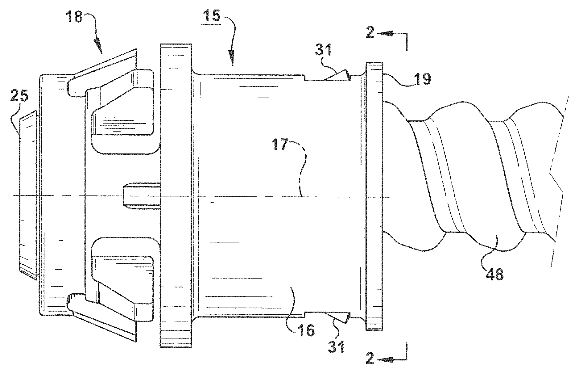
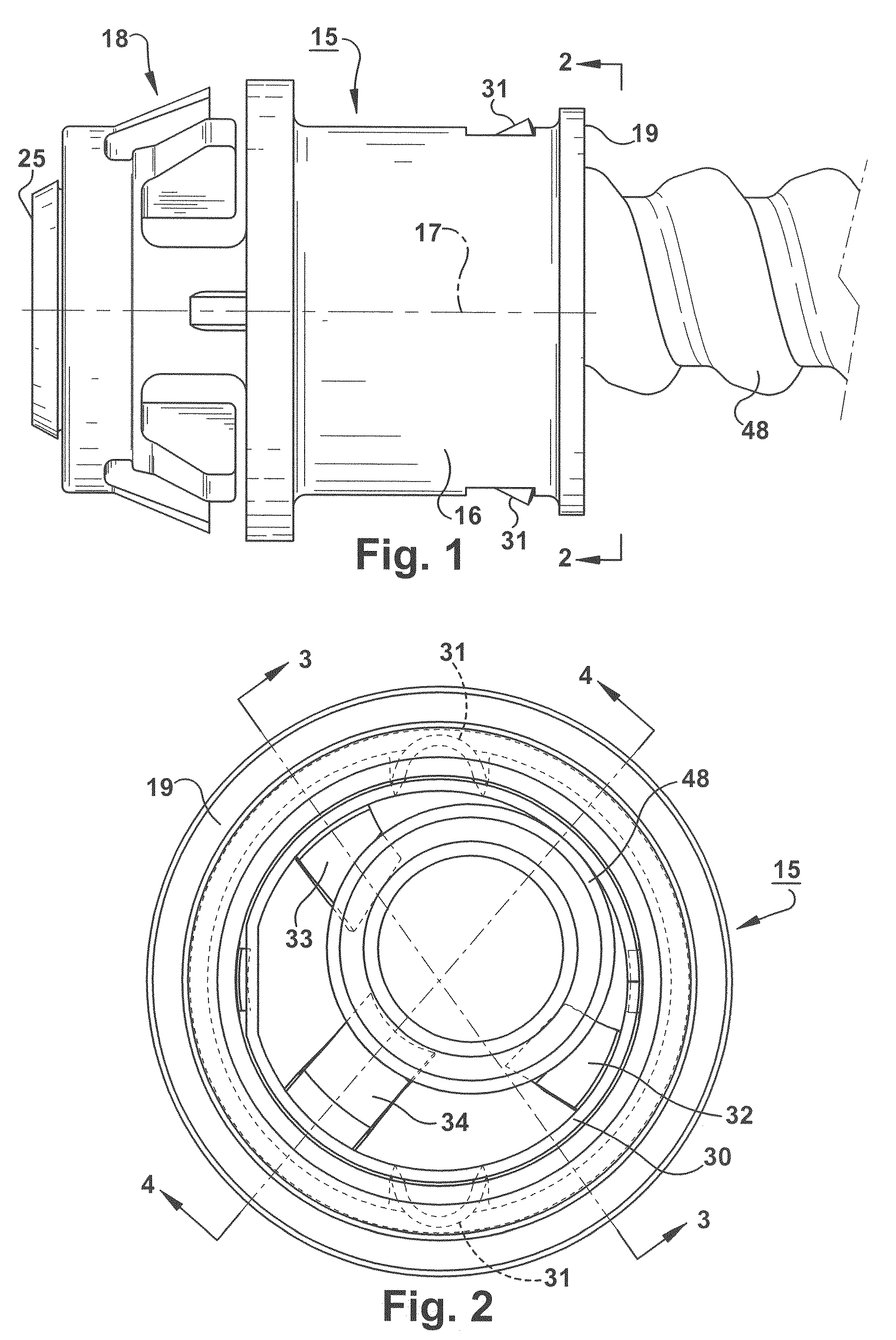
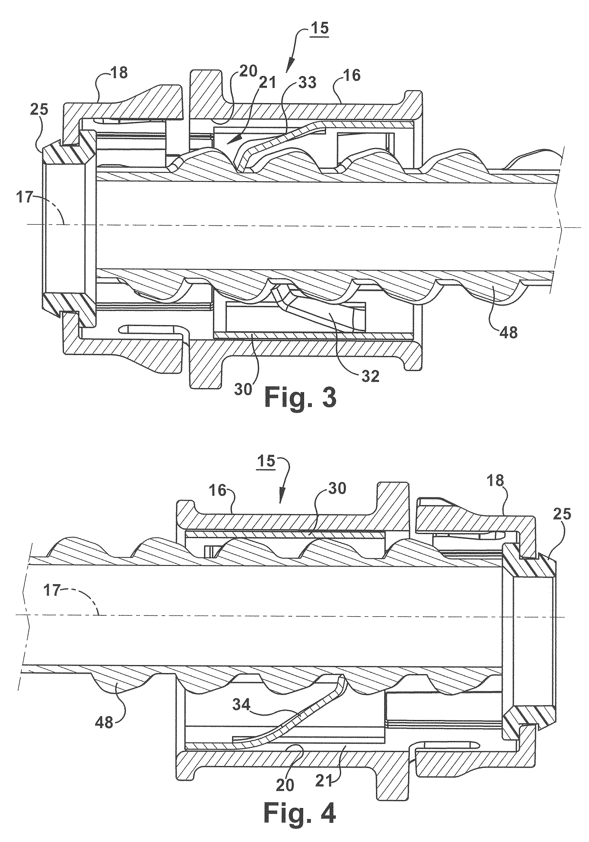
[0030]Referring now to the drawings and to FIGS. 1-12 in particular, the new snap-in connector embodying the present invention is generally indicated by reference numeral 15 in FIG. 1. The connector 15 includes a cylindrical body 16 having a longitudinal axis 17, a leading end 18 and a trailing end 19.

[0031]The leading end or nose 18, which does not form a part of the present invention, may be constructed as disclosed in U.S. Pat. No. 6,827,604, the disclosure of which is incorporated by reference, to provide a quick-connect snap-in connection when pushed through an opening of a junction box. The end opening of the nose 18 is shown provided with an insulated bushing 25. In FIGS. 1-4, reference numeral 48 designates a helical metal cable or conduit that is engaged in the connector 15 in a manner to be described. The cable / conduit wires (not shown) pass through the connector and the bushing 25.

[0032]The connector body 16 has a cylindrical wall 20 that defines a locking ring chamber 21...


PUM


Abstract

In a snap-in electrical connector for attaching helical metal cable and conduit to a junction box or the like, the connector having the locking ring with flexible tabs engageable with the cable / conduit, the improvement wherein the tabs have legs angled inwardly of the ring at specified angles, tips that form specified angles with the legs, and tip ends that are biased relative to the legs in the same direction. The specified angles of the legs, tips and tip ends provide improved pull-out strength, electrical conductivity and stability for a wide range of sizes and types of cable and conduit, including metal clad cable, armored cable, and flexible metal conduit, made of aluminum and steel.

Description

CROSS-REFERENCE TO RELATED APPLICATION[0001]This application is a Continuation-In-Part of U.S. patent application Ser. No. 11 / 422,097 filed Jun. 5, 2006, and is incorporated herein by reference in its entirety.FIELD OF THE INVENTION[0002]The present invention relates generally to electrical connectors, and more specifically to a new and improved snap-in connector for electrical junction boxes and the like.BACKGROUND OF THE INVENTION[0003]The invention is particularly concerned with improvements in snap-in connectors for helical metal cable and conduit, such as metal-clad cable, armored cable and flexible metal conduit. A known connector of this type generally includes a cylindrical body having a leading end that snaps into a hole in the junction box, a trailing end that receives the helical cable / conduit, and inwardly extending, flexible fingers or tangs that are intended to seat in the helical grooves to lock the cable / conduit in the connector body and establish electrical contact....

Claims


Application Information

Patent Timeline
Patent Type & Authority Patents(United States)
IPC IPC(8): H02G3/18
CPCH01R24/564H02G3/0666H02G3/0691H01R2103/00Y10T16/05Y10S439/939Y10T16/063
Inventor GARDNER, MICHAEL J.
Owner HALEXSCOTT FETZER
Why Eureka
Try Eureka