

Image reading apparatus and light source
- Summary
- Abstract
- Description
- Claims
- Application Information
AI Technical Summary
Benefits of technology
Problems solved by technology
Method used
Image

Examples
Embodiment Construction
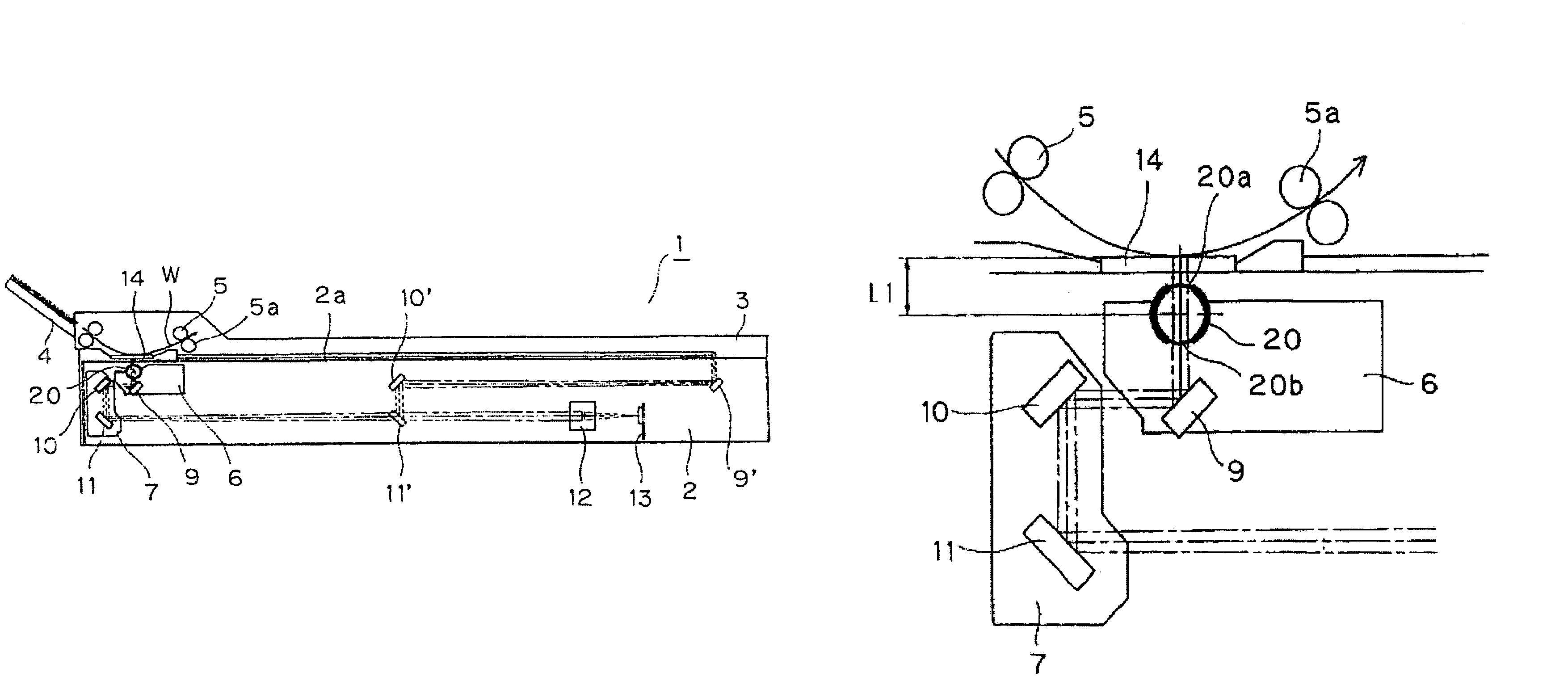
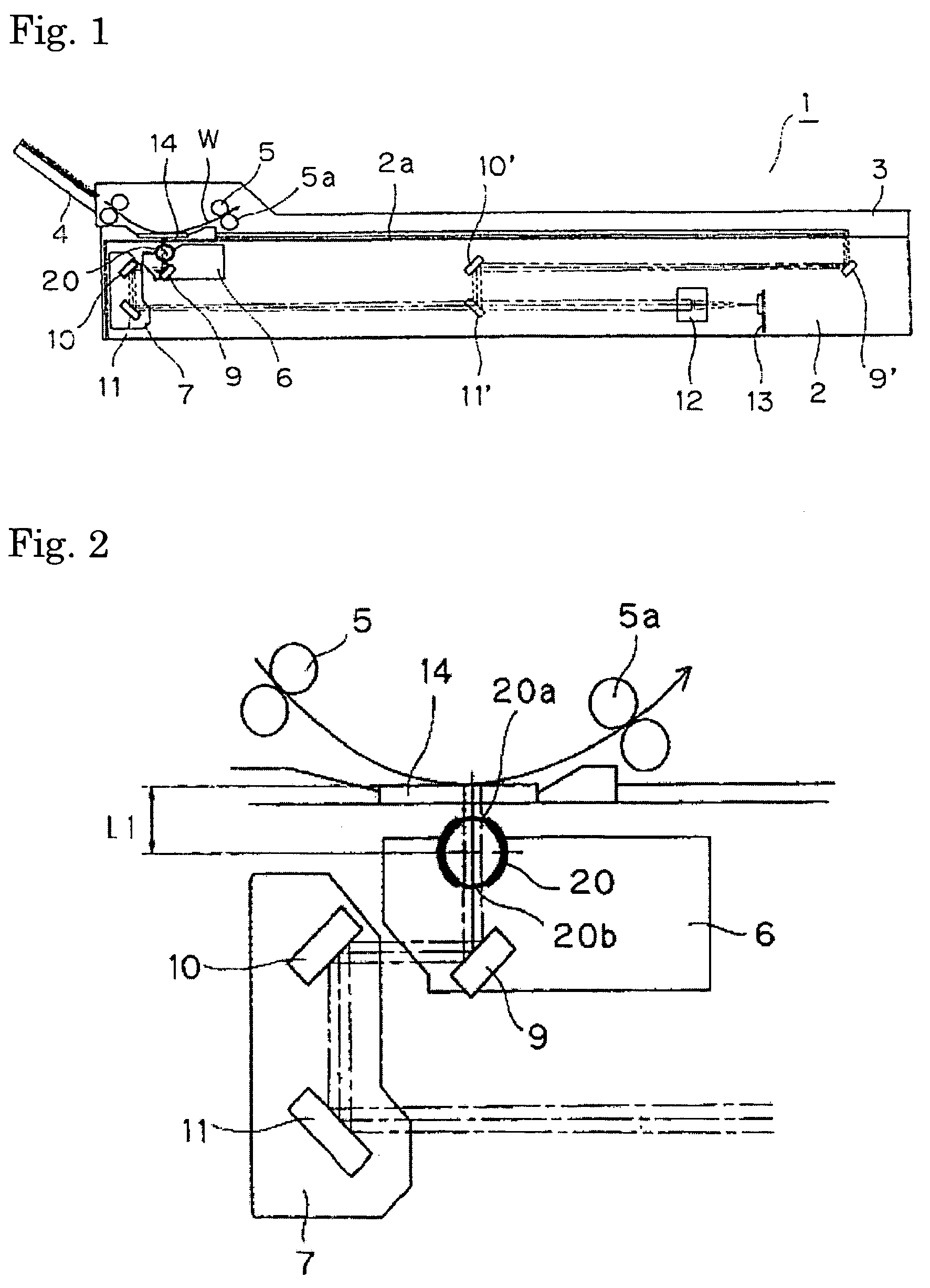
[0037]Embodiments of the present invention are described below with reference to the drawings. FIG. 1 is a cross-sectional side elevation of an image reading apparatus pertaining to a first embodiment. For the sake of simplicity, components identical to those shown in FIGS. 8-10 showing a conventional art apparatus are identified using the same numbers as used therein. The image reading apparatus 1 comprises a main body 2 and a cover 3, which is pivotally supported on the main body 2, such that the cover 3 can be rotated up from the right-hand side in the figure. A conveyance unit 5 that conveys the original document sheet W using rollers 5a is disposed at one end of the cover 3.
[0038]A glass plate 14 is disposed on the surface of the cover 3 below the conveyance unit 5, such that the original document sheet W may be conveyed while remaining in contact with the glass plate 14. A paper supply tray 4 in which the original document sheets W that are supplied to the conveyance unit 5 is...
PUM
 Abstract
Description
Claims
Application Information