Method and arrangement for positioning a patient in a medical diagnosis or therapy device

a technology for diagnosis and therapy, applied in the direction of patient positioning for diagnosis, instruments, applications, etc., can solve the problems of inconvenient use, inability to match the corresponding device, and inability to apply the mark first, so as to achieve less training

Inactive Publication Date: 2008-10-07
SIEMENS HEALTHCARE GMBH
View PDF19 Cites 40 Cited by
  • Summary
  • Abstract
  • Description
  • Claims
  • Application Information

AI Technical Summary

Benefits of technology

[0009]It is an object of the present invention to provide a method that can be implemented simply, and which also enables personnel with less training, to record with fewer operations the desired body region to be examined or to be treated, and to determine the corresponding scan area, whereby an additional topogram recording should be foregone if possible in the implementation. It is also an object of the present invention to provide, a corresponding device for implementation of this simplified method.
[0010]The above are achieved in accordance with the invention wherein the individual body regions, are automatically determined by use of a known image analysis of a recording of the exterior a patient on a patient bed, and wherein such an automatic analysis of the image of a patient is employed for the positioning in a diagnosis device or therapy device. The image of a patient on a bed is automatically analyzed, such that an automatic detection of the individual body regions (for example head, abdomen, chest, and extremities) is made, so that individual scan areas can be subsequently determined. In this manner, it is now possible for the operating personnel to set the scan area by means of a simple selection and / or designation of an automatically determined body region. No deeper anatomical knowledge is required on the part of the operating personnel, beyond merely the indication of the desired body regions to be scanned must be made. If these individual body regions are already shown on the screen and, as the case may be, also automatically indicated by the image processor, a mouse click on an appropriate region or touch upon this region on the touch screen is sufficient to automatically arrange the subsequent scan area necessary for this purpose.
[0014]The operating personnel must merely choose the desired scan areas or scan area in this case. It can be advantageous for the image processor to optically emphasize the region of the recognized body region. This can ensue, for example, by means of a colored marking or a corresponding brightening or hatching on a black and white monitor.
[0016]There is additionally the possibility to manually change the scan area suggested by the image processor, so that possible misinterpretations by the image processor can be corrected.
[0019]The inventive method can be used not only in a single plane with a single image-recording device, but also can be used with two or more image-recording devices having respective recording axes that are independent of one another, preferably orthogonal to each other. It is thus possible to effect not only a 2-dimensional positioning of the patient, but also to position the patient spatially in three dimensions, with in each movement plane of the patient bed having an image-recording device with a recording axis arranged perpendicular to this movement plane. It is possible in this manner to automatically implement a wide range of positioning the patient in 3-dimensional space using at least two image-recording devices. A substantial time savings is achieved due to the automatic determination of the scan area, which is particularly advantageous in the implementation of survey examinations.

Problems solved by technology

It is problematic that a marking first must be applied on the patient by the treating physician or appropriately trained medical personnel.
The application of such markings to the patient can be undesirable for various reasons, so that this method and the corresponding device are not suitable in every situation.
This method is also susceptible to error in the form of individual input error.
In all of the cases cited above, a manual, time-consuming, and less-than-satisfactory interaction is required on the part of the operating personnel, which is regarded as disadvantageous, particularly in survey examinations.

Method used


Image

  • Method and arrangement for positioning a patient in a medical diagnosis or therapy device
  • Method and arrangement for positioning a patient in a medical diagnosis or therapy device
  • Method and arrangement for positioning a patient in a medical diagnosis or therapy device

Examples


Embodiment Construction

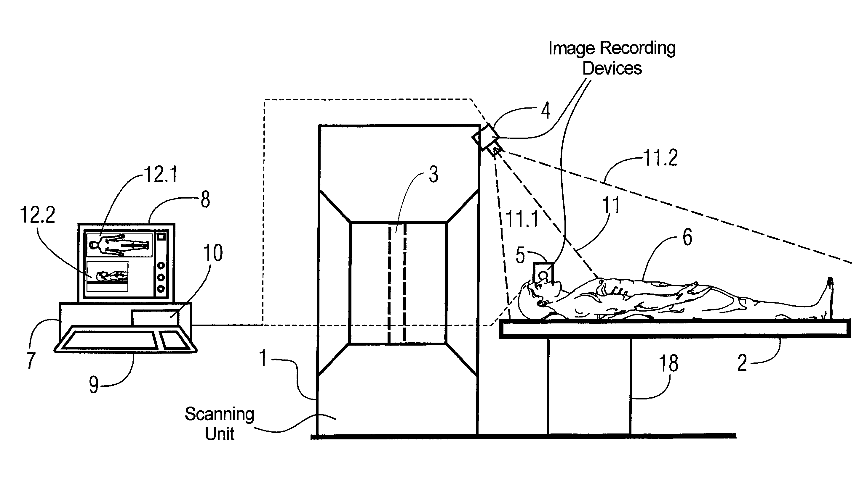
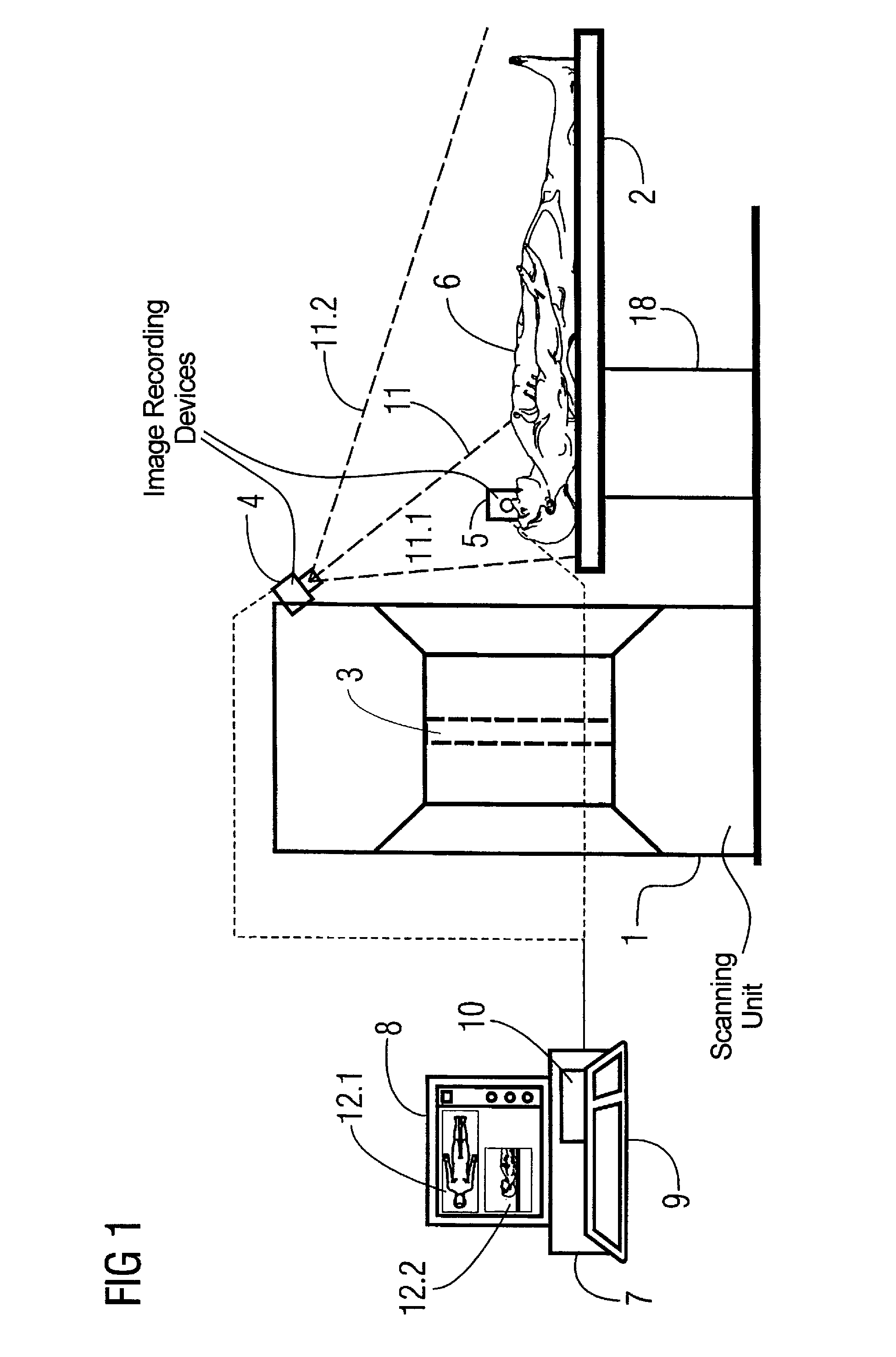
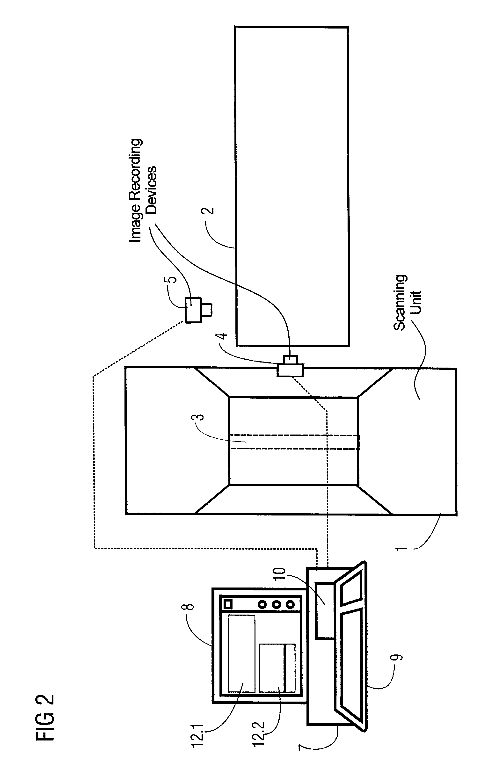
[0033]FIG. 1 shows a side view of a computed tomography apparatus having a scanning unit 1 (gantry), with a bed 2 that can be moved into the scanning unit 1, and a computer 7 that is responsible for the evaluation and control of the computed tomography apparatus.

[0034]The computer 7 has an input keyboard 9, a screen 8, and a storage 10. The images obtained by the recording of the video cameras 4 and 5 are shown in the image sections 12.1 and 12.2 on the screen 8. The video camera 4 is arranged above the patient and provides a frontal image of the patient, while the video camera 5 is arranged laterally to the patient and correspondingly provides a lateral image of the head / chest area of the patient.

[0035]The patient bed 2 is arranged on a movement device 18 that is controlled by the computer 7 in order to appropriately insert the patient on the bed 2 into the scanning unit 1. It should be noted that, for clarity, only the dashed displayed connections between the video cameras 4 and 5...


PUM


Abstract

In a method and a device for positioning a patient in a medical diagnosis device or therapy device, an image-recording device records an image of the patient, which is displayed on a screen, and an image processor aids the positioning of the patient. At least one body region is automatically detected by the image processor, and a scan area is automatically suggested on the screen that covers the body region.

Description

BACKGROUND OF THE INVENTION[0001]1. Field of the Invention[0002]The present invention concerns a method and an arrangement for positioning a patient in a medical diagnosis device or therapy device (medical device) of the type having a unit that interacts with the patient, a computer, and a patient bed that can be adjusted in at least one plane, and at least one image-recording device that acquires an image of the exterior of the patient and displays it on a screen, and an image processor that supervises or controls the positioning of the patient, wherein the computer “knows” the spatial correlation between the coordinate system of the treatment unit and the image-recording device.[0003]2. Description of the Prior Art[0004]A method and arrangement of the above general type are known from German published application 195 08 715. A medical diagnosis device with a method for positioning a patient in this diagnosis device is described in this application, wherein an image-recording devic...

Claims


Application Information

Patent Timeline
Patent Type & Authority Patents(United States)
IPC IPC(8): G06K9/00A61B6/00G21K1/12G01R33/30A61B5/055A61B6/03A61B6/04A61B6/08A61B19/00A61N5/10G01T1/161G21K5/00
CPCA61B5/0555A61B6/08A61B6/469A61B19/5212A61B19/5225A61N2005/1059A61B5/055A61B90/361A61B90/37
Inventor CHEREK, DIETERKAGERMEIER, ROBERTLOSER, MICHAELMEDLAR, DONALSTEINMANN, HENDRIKURMONEIT, UWE
Owner SIEMENS HEALTHCARE GMBH
Why Eureka
Try Eureka