Unitary testing apparatus for performing bit error rate measurements on optical components

a technology of optical components and unit testing apparatus, applied in the field of optical communication systems, can solve the problems of wasting time and money, affecting the accuracy of optical communication system bit error rate measurements,

Active Publication Date: 2008-10-07
TEXAS INSTR INC +1
View PDF15 Cites 13 Cited by
  • Summary
  • Abstract
  • Description
  • Claims
  • Application Information

AI Technical Summary

Benefits of technology

[0015]The present invention is therefore directed to a system for testing the sensitivity of optical components...

Problems solved by technology

Although the technology associated with optical communication systems and components has greatly advanced over the last decade and the use of such technology has accelerated, the technology associated with testing optical communication systems and components has greatly lagged.
An optical communication system is only as fast and reliable as the worst component within the system.
This involves a tedious and time-consuming process that leads to human error.
The assemblage of multiple optical components also poses a problem due to the number of optical interfaces.
It is often tedious to recalibrate the entire opt...

Method used


Image

  • Unitary testing apparatus for performing bit error rate measurements on optical components
  • Unitary testing apparatus for performing bit error rate measurements on optical components
  • Unitary testing apparatus for performing bit error rate measurements on optical components

Examples


Embodiment Construction

[0025]In the following detailed description, for purposes of explanation and not limitation, exemplary embodiments disclosing specific details are set forth in order to provide a thorough understanding of the present invention. However, it will be apparent to one having ordinary skill in the art having had the benefit of the present disclosure, that the present invention may be practiced in other embodiments that depart from the specific details disclosed herein. Moreover, descriptions of well-known devices, methods and materials.

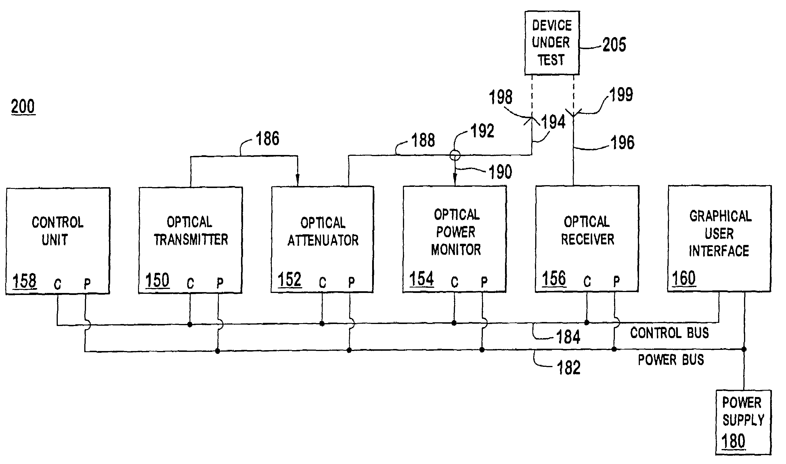
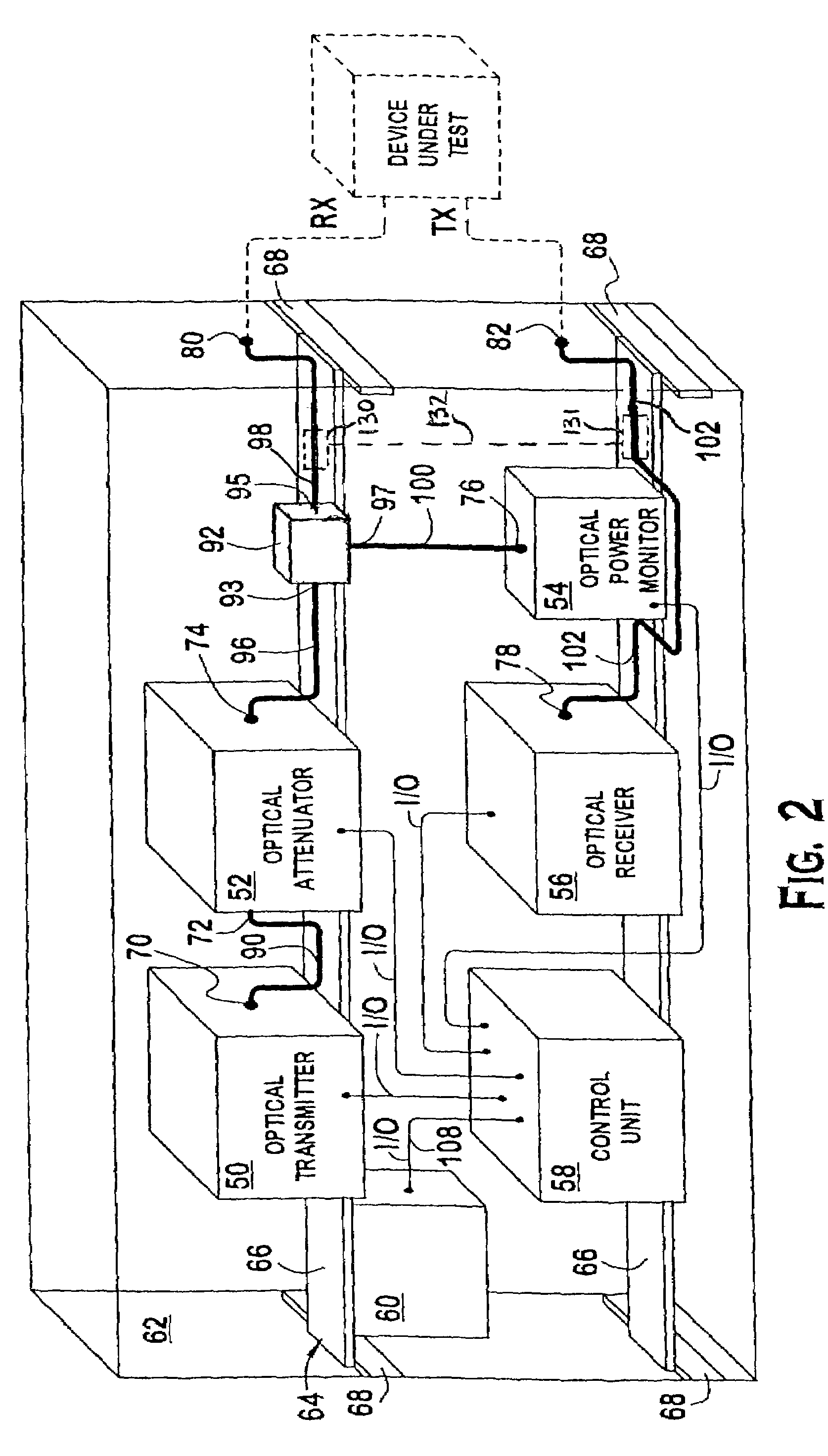
[0026]Referring to FIG. 2, an illustrative embodiment of the testing apparatus of present invention includes an optical transmitter 50, an optical attenuator 52, an optical power monitor 54, an optical receiver 56, a microprocessor (control unit) 58, and an optical splitter 92. A graphical user interface 60 is also illustrated, and may be optionally included in the testing apparatus. Of course, it should be recognized that the optical components are not dra...


PUM


Abstract

A testing apparatus for testing optical components includes an optical transmitter, an optical attenuator, an optical power meter and an optical receiver which are substantially rigidly coupled in a fixed relation to each other within a single housing. The system permits the common control of all the optical components such that calibration, testing and troubleshooting may be performed using a common user interface. The testing apparatus is unitary, compact and portable, and is a much more robust testing apparatus than conventional schemes.

Description

CROSS-REFERENCE TO RELATED APPLICATIONS[0001]The present application claims priority under 35 U.S.C. 120 to PCT / US02 / 06365 filed on Mar. 5, 2002, which is hereby incorporated by reference in its entirety for all purposes.BACKGROUND OF THE INVENTION[0002]1. Field of the Invention[0003]This invention relates generally to optical communication systems. More particularly, the invention pertains to a system for testing optical communication systems, subsystems and components.[0004]2. Description of the Background Art[0005]Opto-electronic components, including fiber optic cables, connectors, transmitters, receivers, switches, routers and all other types of optical components have become the backbone of the modern telecommunication infrastructure. Due to their relatively low error rate and wide bandwidth, optical communication systems have supported an explosion in the growth of data communication systems, such as the Internet. With the Internet in its infancy, it is expected that the reli...

Claims


Application Information

Patent Timeline
IPC IPC(8): G06F11/00G01N21/00G02B6/26H04B10/08
CPCH04B10/07
Inventor FRANKE, JORGE EDUARDOFRENCH, JOHN SARGENTSUN, SHELDON LOUISTHOMPSON, WILLIAM JOSEPH
Owner TEXAS INSTR INC
Why Eureka
Try Eureka