Pulse tube cooler having ¼ wavelength resonator tube instead of reservoir

a technology of resonator tube and cooler, which is applied in the field of pulse tube cryocoolers, can solve the problems of large reservoir mass, low production efficiency, and inability to meet the needs of customers,

Inactive Publication Date: 2008-10-14
SUNPOWER INC
View PDF10 Cites 9 Cited by
  • Summary
  • Abstract
  • Description
  • Claims
  • Application Information

AI Technical Summary

Benefits of technology

[0022]Replacing the reservoir with the resonator tube of the invention has several advantages. There is a large industry that makes tubing so it is a relatively fungible product that is readily and inexpensively available. There is no need to design and fabricate a reservoir to operate at the required pressures and temperatures. The resonator tube 26 encloses a considerably smaller volume and has considerably less mass than a reservoir and therefore not only has less weight and takes up less space, but also there is less mass to be cooled down to operating temperatures on start up when the pulse tube cooler is an upper stage of multiple cascaded stages. Therefore, cool down time is reduced. Because this also greatly reduces the total gas volume in the cooler, less working gas flows through the pulse tube, manifold and regenerator during cool down.

Problems solved by technology

The reservoir, however, also has some undesirable characteristics.
As a consequence the reservoir has a large mass, has a large volume occupying considerable space, is relatively heavy and is relatively expensive to manufacture.
The relatively large mass of the reservoir, and its consequent high heat storage capacity, causes a substantial time delay until the cryocooler reaches operating temperature.

Method used


Image

  • Pulse tube cooler having ¼ wavelength resonator tube instead of reservoir
  • Pulse tube cooler having ¼ wavelength resonator tube instead of reservoir
  • Pulse tube cooler having ¼ wavelength resonator tube instead of reservoir

Examples


Embodiment Construction

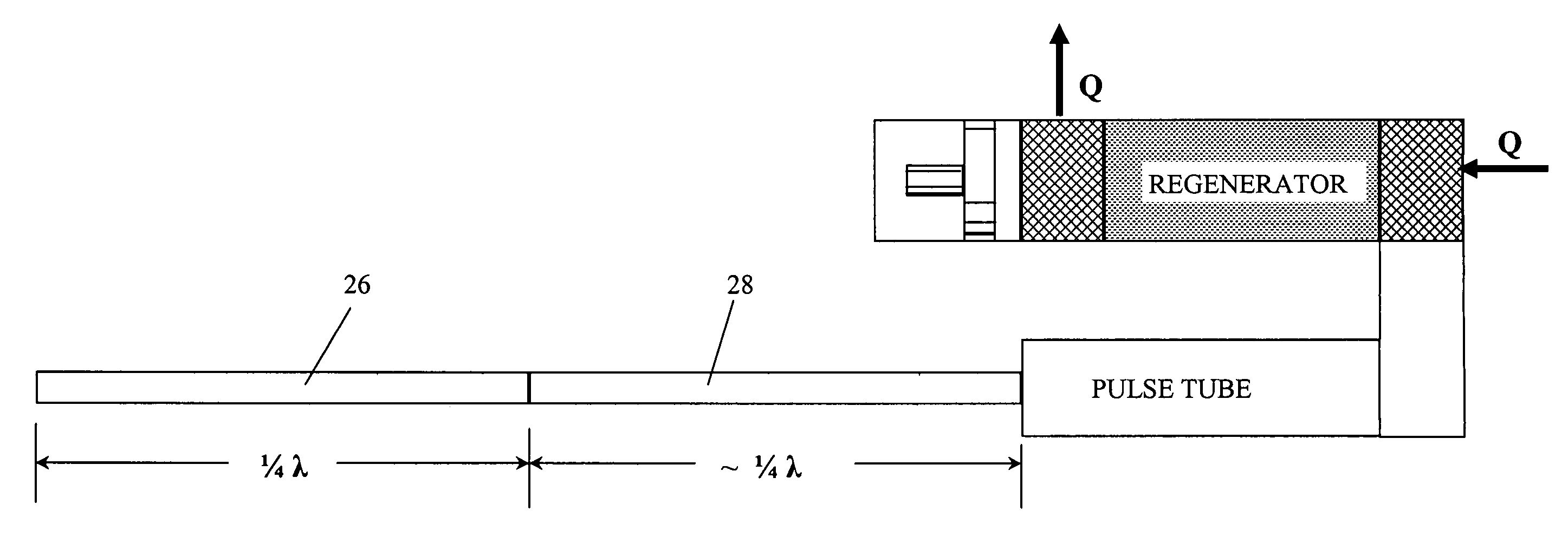
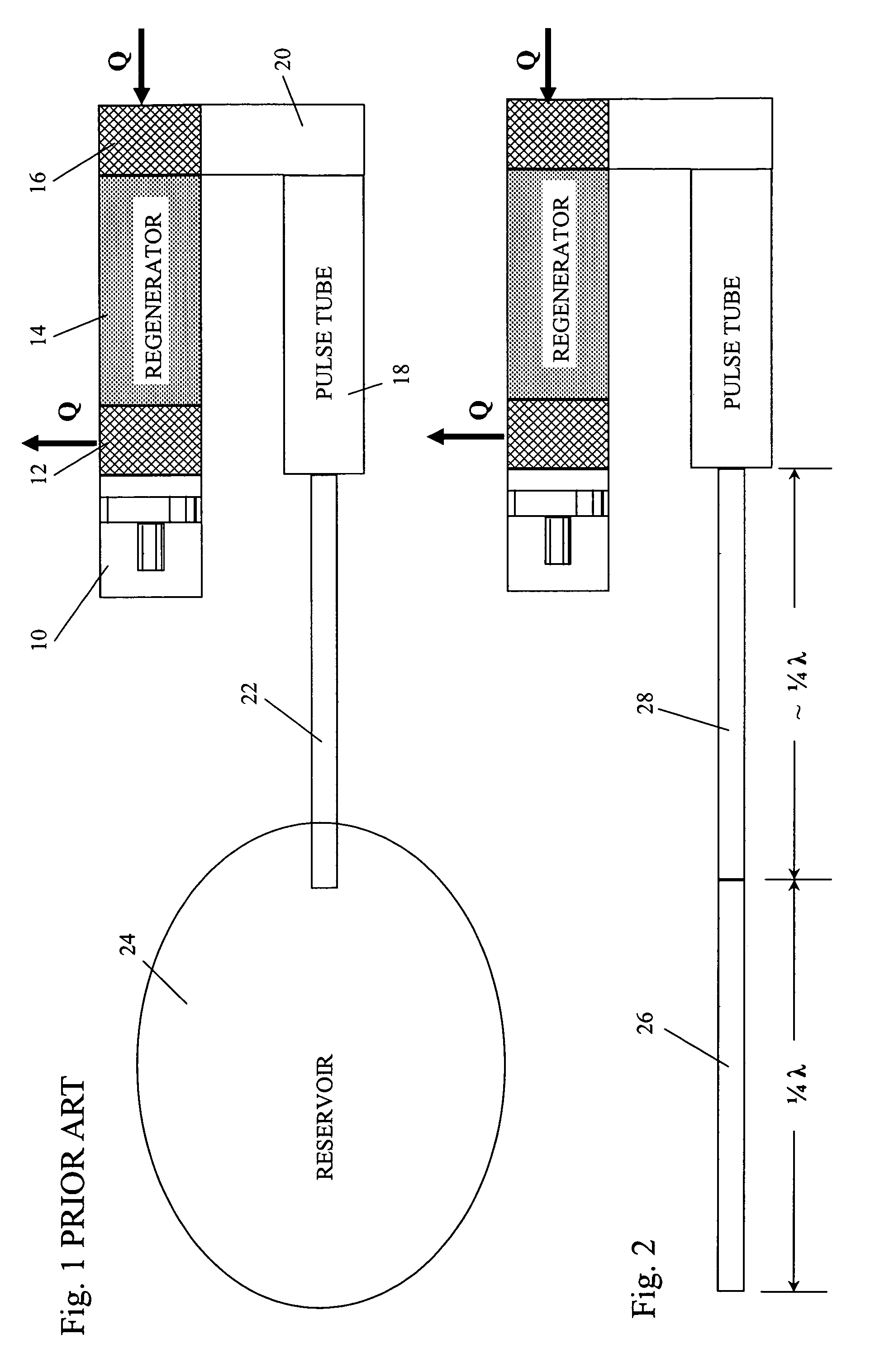
[0019]FIGS. 1 and 2 diagrammatically show pulse tube coolers in a U-tube configuration, although the invention is applicable to linear and other configurations. Those Figs. each show a single stage, but, as known in the art, pulse tube coolers can have multiple stages cascaded with the each stage accepting heat from its immediately subsequent higher stage, or if it is the highest stage from the object being cooled, and rejecting heat to its immediately preceding lower stage, or to the ambient atmosphere, if it is the lowest stage. Therefore, the coolers of FIGS. 1 and 2 also represent individual stages of a cryocooler having multiple, cascaded stages.

[0020]The pulse tube cooler of FIG. 1 is constructed in accordance with the prior art. A pressure wave generator, having a selected operating frequency such as 30 Hz or 60 Hz, is connected through a heat rejecting heat exchanger 12, a regenerator 14 and a heat accepting heat exchanger 16 to one end of a pulse tube 18. The connection fro...


PUM


Abstract

An improved pulse tube cooler having a resonator tube connected in place of a compliance volume or reservoir. The resonator tube has a length substantially equal to an integer multiple of ¼ wavelength of an acoustic wave in the working gas within the resonator tube at its operating frequency, temperature and pressure. Preferably, the resonator tube is formed integrally with the inertance tube as a single, integral tube with a length approximately ½ of that wavelength. Also preferably, the integral tube is spaced outwardly from and coiled around the connection of the regenerator to the pulse tube at a cold region of the cooler and the turns of the coil are thermally bonded together to improve heat conduction through the coil.

Description

(a) STATEMENT REGARDING FEDERALLY-SPONSORED RESEARCH AND DEVELOPMENT[0001]This invention was made with Goverment support under contact NAS5-02021 awarded by NASA. The Goverment has certain rights in this invention.(b) CROSS-REFERENCE TO RELATED APPLICATIONS[0002](Not Applicable)(c) REFERENCE TO AN APPENDIX[0003](Not Applicable)(d) BACKGROUND OF THE INVENTION[0004]1. Field of the Invention[0005]This invention relates generally to pulse tube cryocoolers and more particularly to a structure that can be substituted for the reservoir that is used in common configurations and thereby reduce cost, working gas volume, weight and cool down time.[0006]2. Description of the Related Art[0007]Traveling wave pulse tube coolers have been recognized as having desirable characteristics for cooling to cryogenic temperatures, particularly when multiple coolers are cascaded in stages. Their development began with the study of the cooling effects resulting from the application of a pressure wave to one ...

Claims


Application Information

Patent Timeline
Patent Type & Authority Patents(United States)
IPC IPC(8): F25B9/00
CPCF25B9/145F25B2309/1423F25B2309/1411F25B2309/1408F25B9/00
Inventor GEDEON, DAVID R.
Owner SUNPOWER INC
Why Eureka
Try Eureka