Circuit for reference current and voltage generation

a reference current and voltage generation technology, applied in the direction of electric variable regulation, process and machine control, instruments, etc., can solve the problems of static current consumed in the circuit for reference current and voltage generation, usually a technique bottleneck, and inability to fully turn off the current,

Inactive Publication Date: 2008-10-14
IND TECH RES INST
View PDF16 Cites 6 Cited by
  • Summary
  • Abstract
  • Description
  • Claims
  • Application Information

AI Technical Summary

Benefits of technology

[0010]Therefore, it is an object of the present invention to provide a circuit for reference current and voltage generation that provides complete turn-on and turn-off functions. The circuit hardly consumes any current when it is turned off, thus the usage time of the hand-held electronic apparatus is effectively extended, and the present invention can be embodied merely by the CMOS manufacturing process.
[0014]In accordance with a preferred embodiment of the present invention, in the present invention, a startup circuit is configured to turn on the constant gm bias circuit, and the startup circuit and a constant gm bias circuit are further configured to turn on a voltage reference circuit. Regarding to the turn-off function, in the present invention, a predetermined voltage provided by the isolator is used to turn off the constant gm bias circuit and the voltage reference circuit. Accordingly, the present invention can provide complete turn-on and turn-off functions.
[0015]Moreover, when the circuit is turned off, the isolator of the present invention isolates the startup circuit, the constant gm bias circuit, and the voltage reference circuit, which completely blocks the current. Accordingly, the circuit for reference current and voltage generation provided by the present invention does not consume any current when it is in the turned-off state, which significantly extends the usage time of the hand-held electronic apparatus. Furthermore, since the BJT transistor is not required in the present invention, the present invention can be embodied merely by the CMOS manufacturing process.

Problems solved by technology

For the analog circuit, the static current consumed in the circuit for reference current and voltage generation is usually a technique bottleneck.
However, the startup disabling circuit 102 proposed in this patent cannot fully turn off the current.
In other words, there is still some current consumption when the circuit is in the turned-off state.
However, a method for turning off the circuit is absent.
In summary, the current technique fails to fulfill our expectation.

Method used


Image

  • Circuit for reference current and voltage generation
  • Circuit for reference current and voltage generation
  • Circuit for reference current and voltage generation

Examples


Embodiment Construction

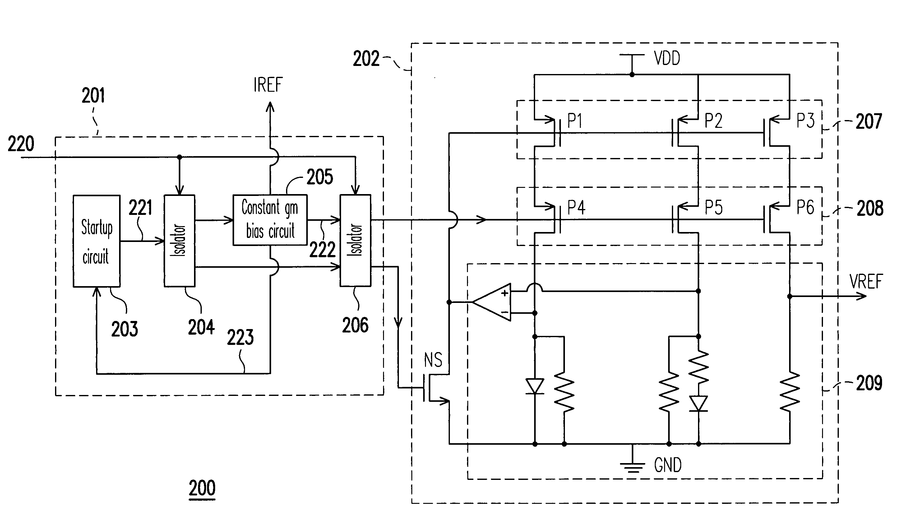
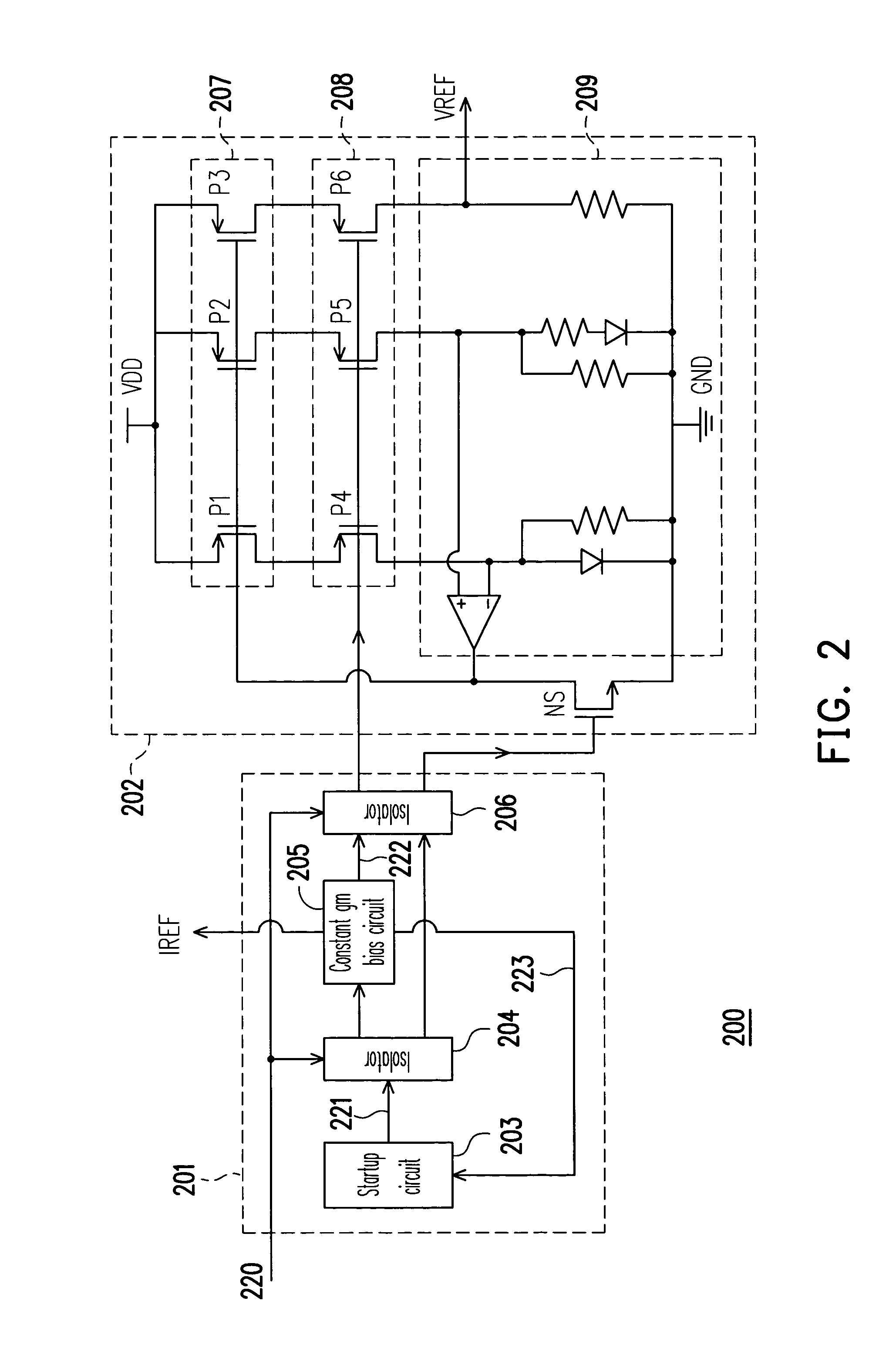
[0021]FIG. 2 is a schematic circuit diagram of a circuit for reference current and voltage generation 200 according to an embodiment of the present invention. The circuit for reference current and voltage generation 200 comprises a current bias circuit 201 and a voltage reference circuit 202 that are electrically coupled with each other.

[0022]The current bias circuit 201 comprises a startup circuit 203, an isolator 204, a constant gm bias circuit 205, and an isolator 206. Wherein, the isolator 204 is electrically coupled to the startup circuit 203. The constant gm bias circuit 205 is electrically coupled to the startup circuit 203 and the isolator 204. The isolator 206 is electrically coupled to the constant gm bias circuit 205 and the isolator 204.

[0023]On the other hand, the voltage reference circuit 202 comprises switch circuits 207 and 208, a startup transistor NS (that is an NMOS transistor in the present embodiment), and a bandgap reference circuit 209. Wherein, the switch cir...


PUM


Abstract

A circuit for reference current and voltage generation is provided. The circuit comprises a current bias circuit and a voltage reference circuit. Wherein, the current bias circuit receives an enable signal, provides a reference current, a bias signal and a startup signal when the enable signal is in an enabling state, and provides a first predetermined voltage and a second predetermined voltage when the enable signal is in a disabling state. The voltage reference circuit is electrically coupled to the current bias circuit. In addition, the voltage reference circuit enters into a turned-on state and provides a reference voltage after receiving the bias signal and the enable signal, and enters into a turned-off state after receiving the first and the second predetermined voltages.

Description

CROSS-REFERENCE TO RELATED APPLICATION[0001]This application claims the priority benefit of Taiwan application serial No. 94127991, Aug. 17, 2005. All disclosure of the Taiwan application is incorporated herein by reference.BACKGROUND OF THE INVENTION[0002]1. Field of the Invention[0003]The present invention relates to a circuit for reference current and voltage generation, and more particularly, to a circuit for reference current and voltage generation used in a hand-held electronic device.[0004]2. Description of the Related Art[0005]Since the application of hand-held electronic devices is more popular now, the requirement of the battery usage time is more demanded. How to reduce the power consumed by the electronic components in the hand-held electronic apparatus when it is in a stand-by or turned-off state had become a major subject of the current technology development. For the analog circuit, the static current consumed in the circuit for reference current and voltage generatio...

Claims


Application Information

Patent Timeline
Patent Type & Authority Patents(United States)
IPC IPC(8): G05F3/16
CPCG05F3/30
Inventor LIN, CHUNG-WEI
Owner IND TECH RES INST
Why Eureka
Try Eureka