Piecewise on-time modulation apparatus and method for a power factor corrector

a power factor and on-time modulation technology, applied in the direction of electric variable regulation, process and machine control, instruments, etc., can solve the problems of affecting the total harmonic distortion of the system, affecting the efficiency of the power factor correction process, and possibly exceeding the rating of the demand for consumption as required, etc., to achieve the effect of reducing the charging current, increasing the on-time, and prolonging the charging tim

Active Publication Date: 2008-10-14
RICHTEK TECH
View PDF8 Cites 16 Cited by
  • Summary
  • Abstract
  • Description
  • Claims
  • Application Information

AI Technical Summary

Benefits of technology

[0009]Yet another object of the present invention is to provide a power factor corrector and method thereof that are capable of reducing the total harmonic distortion of the system.
[0012]In the circumstances that the reference voltage varies as the line voltage changes, when the line voltage is lower than a threshold, the reference voltage decreases as the line voltage increases. If the charging current is constant, i.e., the output voltage is fixed, the reference voltage increases as the line voltage decreases, and the charging time for the charged voltage to reach the reference voltage becomes longer and therefore the PWM switch has a longer on-time, such that more energy is drawn from the input capacitor. When the line voltage is equal to or higher than the threshold, the voltage source keeps the reference voltage constant, and thus the on-time of the PWM switch is also constant. Furthermore, since the charging current is generated based on the output voltage, the charging current decreases as the output voltage decreases, and accordingly, a longer charging time is required for the charged voltage to reach the reference voltage. Consequently, a longer time is induced for the line current to charge the boost capacitor, thereby achieving the output voltage regulation.

Problems solved by technology

Specifically, in an AC-to-DC converter, for electronic apparatus requesting large power, the power consumption as demanded possibly exceeds the rating, thereby having potentially interference upon other electronic apparatus.
As a result, the total harmonic distortion of the system is serious.

Method used


Image

  • Piecewise on-time modulation apparatus and method for a power factor corrector
  • Piecewise on-time modulation apparatus and method for a power factor corrector
  • Piecewise on-time modulation apparatus and method for a power factor corrector

Examples


Embodiment Construction

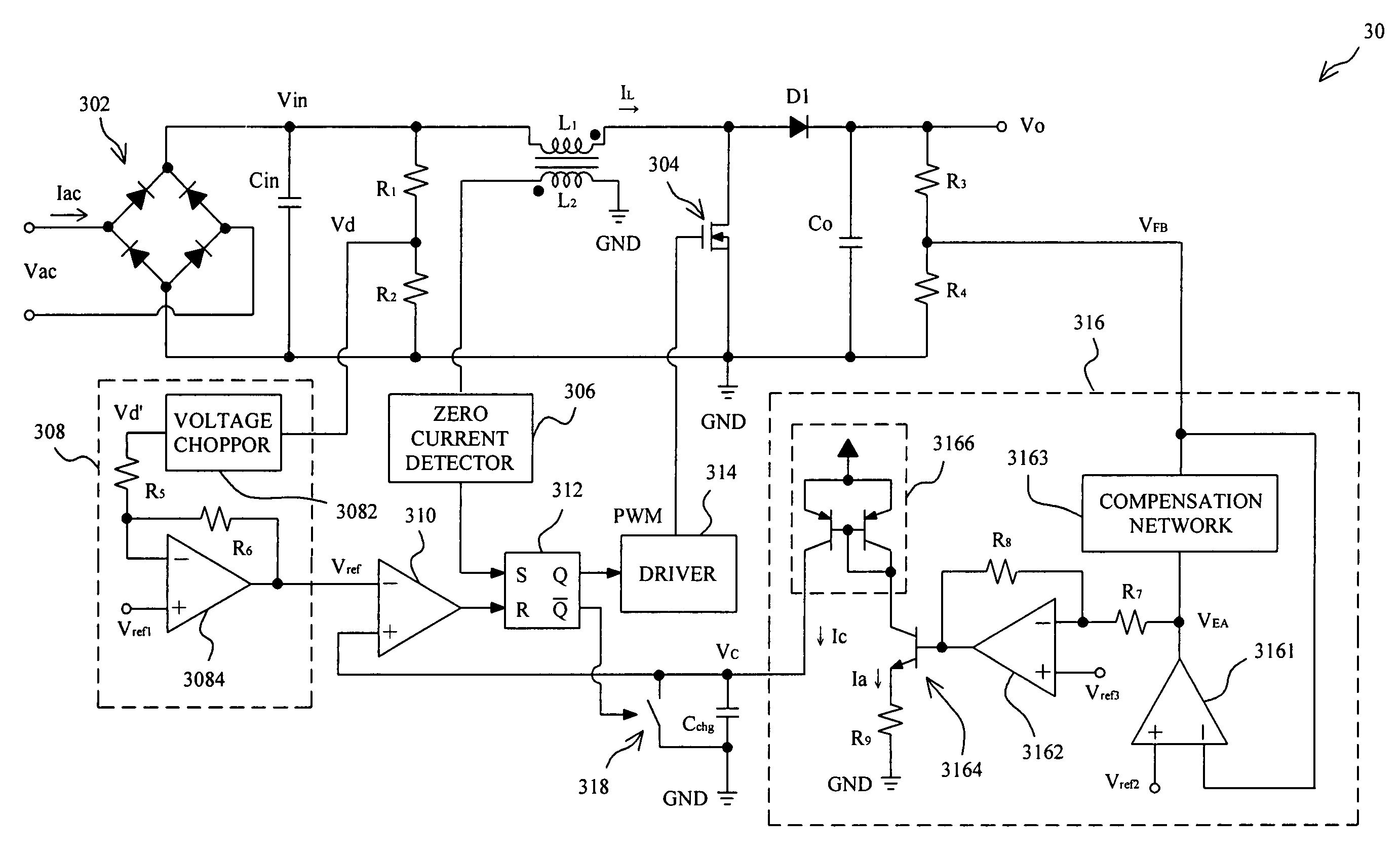
[0028]FIG. 4 shows a power factor corrector 30 according to the present invention. A bridge rectifier 302 converts an AC input voltage Vac to a line voltage Vin coupled to an inductor L1 to generate a line current IL to charge a boost capacitor CO to generate an output voltage VO. The power factor corrector 30 comprises a transistor 304 as a PWM switch connected between the inductor L1 and ground GND to switch the line current IL to the boost capacitor CO or to ground GND. In the power factor corrector 30, a voltage source 308 generates a reference voltage Vref based on the line voltage Vin, a current source 316 generates a charging current IC based on the output voltage VO to charge a capacitor Cchg to thereby generate a charged voltage VC thereon, and a comparator 310 compares the charged voltage VC with the reference voltage Vref to generate a comparison signal coupled to the reset input R of an RS latch 312. When the charged voltage VC on the capacitor Cchg is equal to or higher...


PUM


Abstract

In a power factor corrector including a PWM switch to switch a line current generated from a line voltage to charge a boost capacitor to thereby generate an output voltage, a piecewise on-time modulation apparatus and method comprise comparing a line voltage dependent voltage with an output voltage dependent voltage to generate a comparison signal to determine the on-time of the PWM switch. When the line voltage is lower than a threshold, the on-time of the PWM switch varies with the line voltage, and when the line voltage is higher than the threshold, the on-time of the PWM switch is constant.

Description

FIELD OF THE INVENTION[0001]The present invention is related generally to a power factor correction (PFC) and more particularly, to a piecewise on-time modulation apparatus and method for power factor improvement.BACKGROUND OF THE INVENTION[0002]Power converter is almost an indispensable part for various electronic apparatus. Specifically, in an AC-to-DC converter, for electronic apparatus requesting large power, the power consumption as demanded possibly exceeds the rating, thereby having potentially interference upon other electronic apparatus. Therefore, power factor correction may be critical to electronic apparatus, since it may achieve functions of energy saving or power consumption reduction and efficiently reduce harmonic distortion occurred resulting in power contamination. The power factor reflects a relationship between an effective power and a total power consumption (i.e., apparent load power), and specifically the ratio of the effective power to the total power consump...

Claims


Application Information

Patent Timeline
Patent Type & Authority Patents(United States)
IPC IPC(8): H02M3/335H02M1/42
CPCH02M1/4225Y02B70/126H02M2001/0022Y02B70/10Y02P80/10H02M1/0022
Inventor LI, HONG-CHUNTSAY, CHEAN-LUNGCHEN, DAN
Owner RICHTEK TECH
Why Eureka
Try Eureka