OFDM receiving apparatus and receiving method thereof

a technology of receiving apparatus and receiving method, which is applied in the field of receiving apparatus, can solve the problems of affecting the frequency characteristic of transmission based on the ofdm system, remarkably deteriorating the quality of transmission signals, and unable to say, etc., and achieves the effect of improving the frequency characteristi

Inactive Publication Date: 2008-10-14
SONY CORP
View PDF5 Cites 6 Cited by
  • Summary
  • Abstract
  • Description
  • Claims
  • Application Information

AI Technical Summary

Benefits of technology

[0024]In addition, what is also needed is an optimum OFDM receiving apparatus and a receiving method thereof for performing selective diversity receiving for signals received by a plurality of antenna elements for each sub-carrier so as to improve a frequency characteristic of the reception signals.
[0049]The present invention proposes an OFDM receiving apparatus having a sub-carrier selectively combining mode and an antenna selecting mode. The sub-carrier selectively combining mode is configured to selectively combine signals for each sub-carrier. The antenna selecting mode is configured to select a receiving antenna. The OFDM receiving apparatus operates in a proper operation mode based on a communication environment. As a result, in a poor communication environment, signals are selectively combined for each sub-carrier. However, in a relatively satisfactory communication environment, unnecessarily operation of an RF and IF circuit, an A / D converter, and a DDT connected to each receiving antenna may be avoided.

Problems solved by technology

However, when wireless transmission is performed in a mobile transmission environment, the quality of transmission signals is remarkably deteriorated due to fading.
However, it cannot be said that transmission based on the OFDM system has a strong resistance against flat fading in which the delay time difference between incoming waves is small.
As a result, burst errors take place.
As a result, the circuit scale of the apparatus becomes large.
In addition, when the demodulation and the DFT are operated in all the receiving systems, the power consumption of the entire receiving apparatus becomes considerably large.
As a result, it would be redundant to operate all the receiving systems.

Method used


Image

  • OFDM receiving apparatus and receiving method thereof
  • OFDM receiving apparatus and receiving method thereof
  • OFDM receiving apparatus and receiving method thereof

Examples


Embodiment Construction

[0057]Preferred embodiments of the present invention will be described below, with reference to the accompanying drawings.

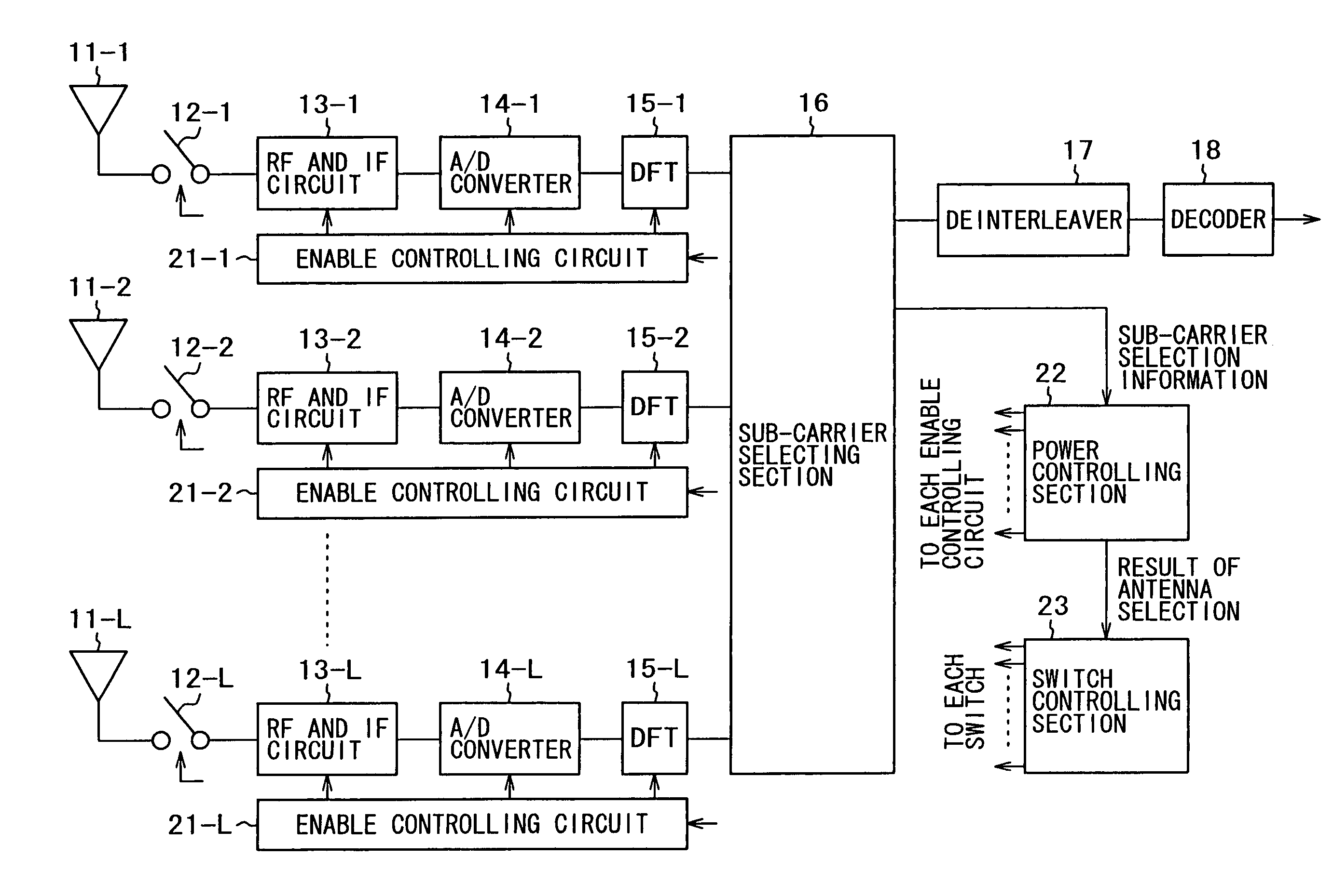
[0058]FIG. 4 schematically shows a structure of an Orthogonal Frequency Division Multiplexing (OFDM) receiving apparatus according to a preferred embodiment of the present invention. As it will be described later, the OFDM receiving apparatus has a sub-carrier selectively combining mode and an antenna selecting mode. The sub-carrier selectively combining mode is configured to selectively combine (which may conveniently mean select and combine) signals for each sub-carrier. The antenna selecting mode is configured to select an antenna element for receiving a signal.

[0059]Antenna elements 11-1 to 11-L have respective directivities that differ from each other. The antenna elements 11-1 to 11-L receive OFDM transmission signals. The reception signals are supplied to RF and IF circuits 13-1 to 13-L through open / close switches 12-1 to 12-L, respectively. In a period of...


PUM


Abstract

An Orthogonal Frequency Division Multiplexing (OFDM) receiving apparatus having a sub-carrier selectively combining mode and an antenna selecting mode. The sub-carrier selectively combining mode is configured to selectively combine signals for each sub-carrier. The antenna selecting mode is configured to select a receiving antenna. The OFDM receiving apparatus operates in a proper operation mode based on a communication environment. As a result, in a poor communication environment, signals are selectively combined for each sub-carrier. However, in a relatively satisfactory communication environment, unnecessarily operation of an RF and IF circuit, an A / D converter, and a DDT connected to each receiving antenna may be avoided.

Description

CROSS REFERENCE TO RELATED APPLICATIONS[0001]The present document is based on Japanese Priority Application JP2003-065374, filed in the Japanese Patent Office on Mar. 11, 2003, the contents in which being incorporated herein by reference to the extent permitted by law.BACKGROUND OF THE INVENTION[0002]1. Field of the Invention[0003]The present invention relates to a receiving apparatus based on Orthogonal Frequency Division Multiplexing (OFDM) in which frequencies of sub-carriers are orthogonally assigned each other in each symbol period, in particular, to an OFDM receiving apparatus and a receiving method thereof for performing diversity receiving so as to obtain a channel characteristic that allows a second or later delay wave to be cancelled or weakened.[0004]More specifically, the present invention relates to an OFDM receiving apparatus and a receiving method thereof for performing selective diversity receiving for signals with a plurality of antenna elements for each sub-carrier...

Claims


Application Information

Patent Timeline
Patent Type & Authority Patents(United States)
IPC IPC(8): H04B7/08H04J11/00H04B7/005H04L27/26
CPCH04B7/0874H04L27/2647H04W52/42
Inventor SANADA, YUKITOSHIABE, MASAYOSHI
Owner SONY CORP
Why Eureka
Try Eureka