Enhanced remote jog handle

a remote jog handle and enhanced technology, applied in the field of machine tools, can solve the problems of reduced functionality, unsatisfactory operators of the manpower in which these tools are controlled, and the remote jog handle is not always ideal for the operator, and achieves the effect of smooth variation of the speed of the movemen

Active Publication Date: 2008-10-14
HAAS AUTOMATION
View PDF8 Cites 11 Cited by
  • Summary
  • Abstract
  • Description
  • Claims
  • Application Information

AI Technical Summary

Benefits of technology

[0005]The present invention solves the foregoing problems by providing a control system for machine tools which allows an operator to smoothly vary the speed of a movement of the machine tool in an intuitive manner. A “shuttle” or throttle style control input is provided, whereby the speed of a movement of the machine tool (in any axis, whether linear, rotary, or a combination thereof) can be varied corresponding to a degree of movement of the control input.

Problems solved by technology

Computer numerical control (“CNC”) machine tools provide a high degree of precision for machining workpieces into a virtually limitless variety of shapes and sizes, but the manner in which these tools are controlled is not always ideal for the operator.
Nevertheless, these remote jog handles suffer from a number of drawbacks, including confusing inputs that require an operator direct his gaze away from the workpiece to input a command and reduced functionality.
Whether located on a remote jog handle or on the main control, these systems are limited by the rigidity of their controls, which only allow an operator to move or “jog” a machine tool in fixed increments.

Method used


Image

  • Enhanced remote jog handle
  • Enhanced remote jog handle
  • Enhanced remote jog handle

Examples


Embodiment Construction

[0016]In the following detailed description, numerous specific details are set forth to provide a full understanding of the present invention. It will be apparent, however, to one ordinarily skilled in the art that the present invention may be practiced without some of these specific details. In other instances, well-known structures and techniques have not been shown in detail to avoid unnecessarily obscuring the present invention.

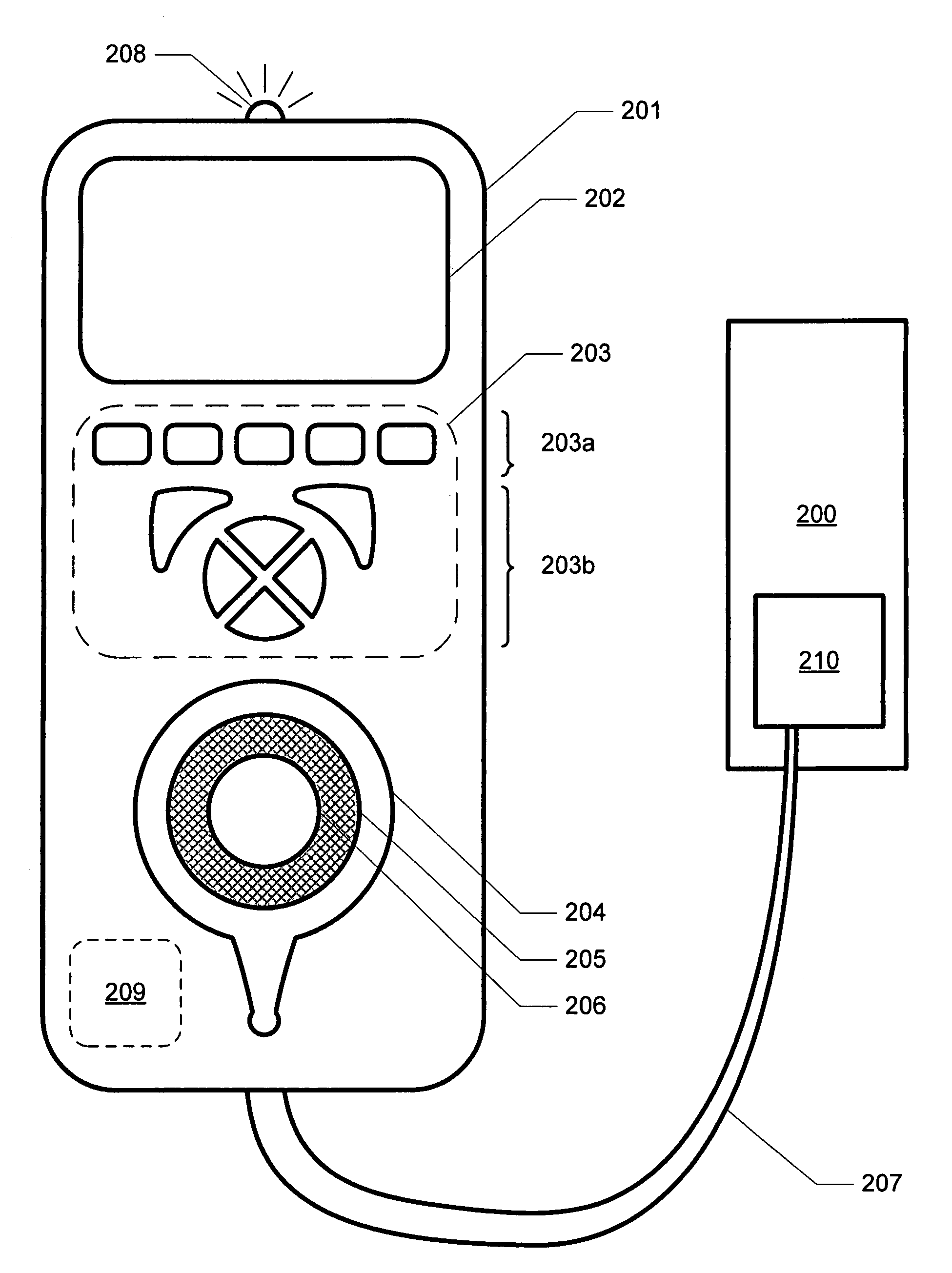
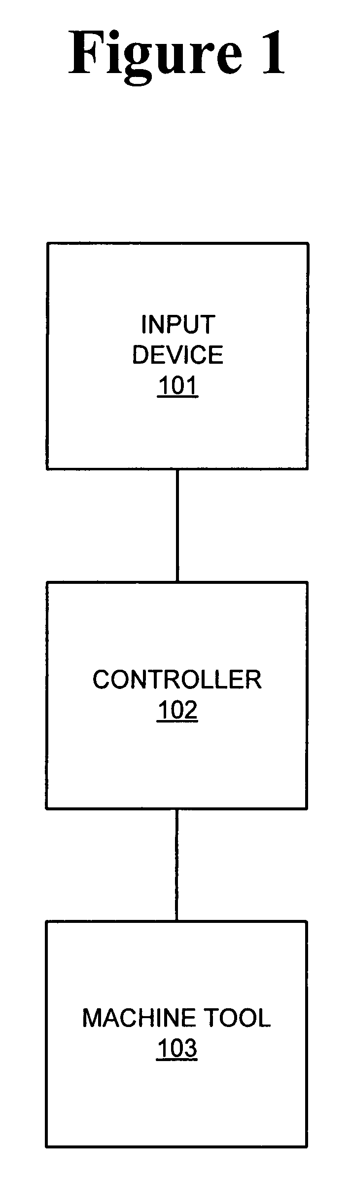
[0017]FIG. 1 is a block diagram illustrating a machine tool system according to one embodiment of the present invention. The system includes an input device 101 that accepts input from an operator, a controller 102 for outputting control signals responsive to the operation of input device 101, and a machine tool 103. Input device 101 is deflectable from a neutral position in an axis of deflection (e.g., a rotatable knob, a slidable switch, a joystick, etc.), and is self-centering (e.g., in the absence of operator input, input device 101 returns to the neu...


PUM


Abstract

A system for controlling a machine tool is provided. The system includes a user input device deflectable from a neutral position and a controller configured to receive information corresponding to an amount of deflection of the user input device from the neutral position and to output a control signal to control a movement of the machine tool in an axis of movement at a rate corresponding to the amount of deflection of the user input device from the neutral position. A machine is provided, including a work tool movable along an axis of movement and a control system including a user input device deflectable from a neutral position and a controller configured to receive information corresponding to an amount of deflection of the user input device from the neutral position and to output a control signal to control a movement of the work tool in an axis of movement at a rate corresponding to the amount of deflection of the user input device from the neutral position.

Description

CROSS-REFERENCE TO RELATED APPLICATION[0001]Not applicable.STATEMENT REGARDING FEDERALLY SPONSORED RESEARCH OR DEVELOPMENT[0002]Not applicable.FIELD OF THE INVENTION[0003]The present invention generally relates to machine tools, and, in particular, relates to systems for controlling machine tools.BACKGROUND OF THE INVENTION[0004]Computer numerical control (“CNC”) machine tools provide a high degree of precision for machining workpieces into a virtually limitless variety of shapes and sizes, but the manner in which these tools are controlled is not always ideal for the operator. Some tools require an operator to control the machine tool from a main control, out of sight of the workpiece. Other systems provide a remote jog handle, which allows an operator to input commands to the machine tool from a more convenient location. Nevertheless, these remote jog handles suffer from a number of drawbacks, including confusing inputs that require an operator direct his gaze away from the workpi...

Claims


Application Information

Patent Timeline
Patent Type & Authority Patents(United States)
IPC IPC(8): G06F19/00G05B15/00G05B19/00
CPCG05B19/409G06F3/0362G05B2219/35456G05B2219/35459G05B2219/50048
Inventor HAAS, GENE F.TANDROW, WILLIAM F.WOOD, ERIC R.WOLF, DAVID E.TEITEL, MICHAEL A.MCINTYRE, BRYAN S.CRICK, ANDY P.
Owner HAAS AUTOMATION
Why Eureka
Try Eureka