Ceramic honeycomb structural body

a technology of ceramic honeycomb and structural body, which is applied in the direction of machines/engines, chemical/physical processes, domestic applications, etc., can solve the problems of cracking of ceramic honeycomb structural body and generation of temperature differen

Active Publication Date: 2008-10-21
IBIDEN CO LTD
View PDF60 Cites 77 Cited by
  • Summary
  • Abstract
  • Description
  • Claims
  • Application Information

AI Technical Summary

Benefits of technology

[0009]According to one embodiment of the present invention, there is provided a ceramic honeycomb structural body comprised of an assembly formed by binding and integrating a plurality of pillar-shaped porous honeycomb ceramic members each having number of cells, juxtaposed to each other in parallel relationship in the longitudinal direction and defined by cell walls , wherein a cross section area perpendicular to the longitudinal direction at each end portion of the porous honeycomb ceramic member is made larger than that at the center portion in the longitudinal direction of the member.

Problems solved by technology

That is, when a ceramic honeycomb structural body is made large by integrally molding, even if silicon carbide having high heat resistance, excellent mechanical characteristics and large thermal conductivity is used as a ceramic member, temperature difference is generated in the ceramic honeycomb structural body by temperature change and local heat generation of exhaust gas, and the ceramic honeycomb structural body tends to be cracked by thermal expansion difference due to this temperature difference.

Method used


Image

  • Ceramic honeycomb structural body
  • Ceramic honeycomb structural body
  • Ceramic honeycomb structural body

Examples


examples

[0036]The present invention will be further explained in detail by referring to examples, but the present invention is not limited to these examples.

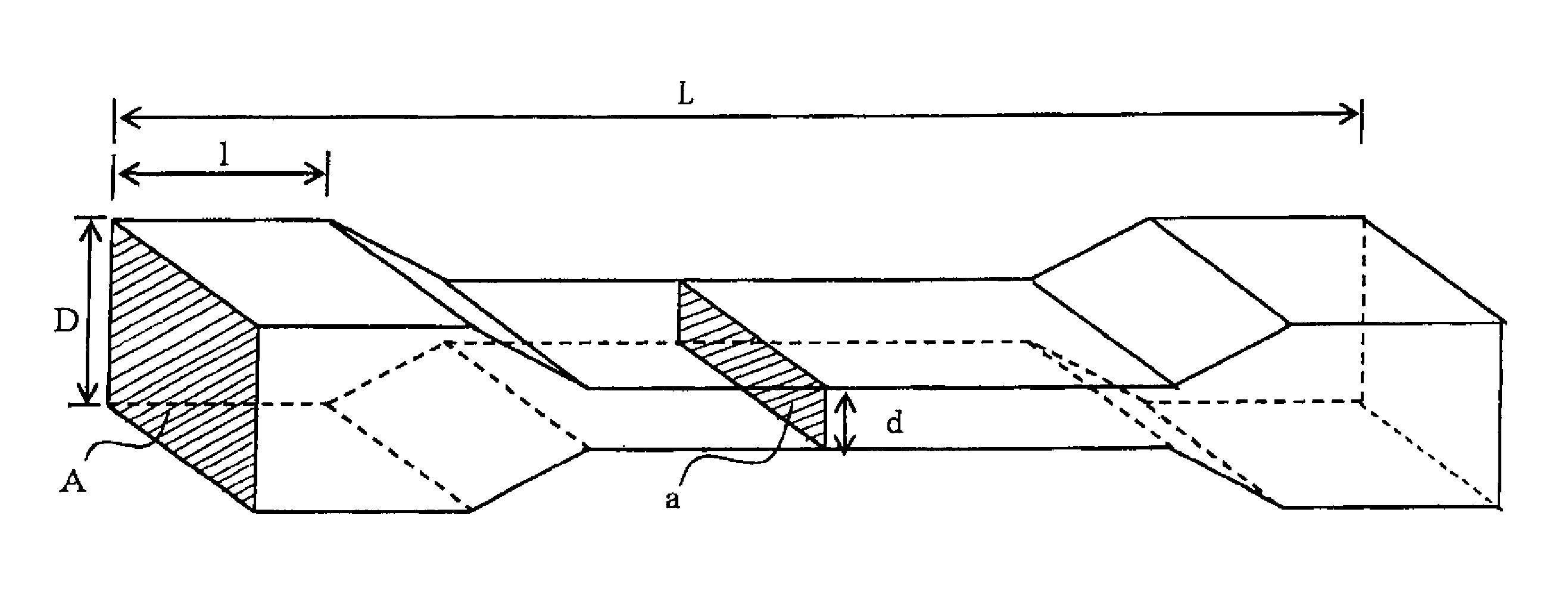
[0037]This example was conducted for confirming function and effect of the ceramic member given to a withstanding push strength (push strength resistance) by a ratio (2×1 / L) of each end region length (2×1) to whole length (L) of the ceramic member and a ratio (A / a) of a cross section area(A)at each end portion to a cross section area (a) at the center portion of the ceramic member. A schematic diagram of the ceramic member used for the present example is shown in FIG. 4. Further, Examples 1 to 6 and Comparative Example 1 and 2 are collectively shown in Table 1. Besides, a method of manufacturing a ceramic member will be described as follows.

[0038]First, to raw material comprising 70 weight parts of silicon carbide raw material powder having about 22 μm of a mean particle diameter and 30 weight parts of silicon carbide raw material powde...


PUM

PropertyMeasurementUnit
flatnessaaaaaaaaaa
mean particle diameteraaaaaaaaaa

Abstract

In the ceramic honeycomb structural body comprised of an assembly formed by assembling and integrating a plurality of pillar-shaped porous honeycomb ceramic members, each member comprising numbers of cells juxtaposed in parallel to the longitudinal direction and defined by cell walls, the cross section area perpendicular to the longitudinal direction at each end portion of the members is made larger than that at the center portion of the member.

Description

CROSS REFERENCE TO RELATED APPLICATION[0001]The present application is based on an International application No.PCT / JP2006 / 301903 filed on Jan. 30, 2006, claiming a priority of Japanese patent application No. 2005-28942 filed on Feb. 4, 2005. The contents of these applications are incorporated herein by reference in its entirety.TECHNICAL FIELD[0002]The present invention relates to a ceramic honeycomb structural body.BACKGROUND ART[0003]Exhaust gas exhausted from internal combustion engines of vehicles such as buses, trucks or construction machines contains particulate and noxious gas having a noxious influence on environments and human bodies. Therefore, in recent years, there is proposed techniques for collecting and removing the particulate from exhaust gas. One of these techniques provides a ceramic structural body used as a filter for purifying the exhaust gas. This ceramic structural body comprises a honeycomb structural porous ceramic member, and embodied as a ceramic honeyco...

Claims


Application Information

Patent Timeline
Patent Type & Authority Patents(United States)
IPC IPC(8): B32B3/12
CPCB01J35/04C04B28/24C04B35/565C04B35/573C04B37/005C04B38/0009C04B38/0019B01D46/2455F01N13/017C04B38/0054C04B38/0074C04B38/0645C04B14/328C04B14/4625C04B24/383B01D46/2451Y10T428/24149B01D46/2459B01D46/2466B01D46/2474B01D2046/2477B01D2046/2481B01D2046/2496C04B2111/00793C04B2235/3826C04B2235/5436C04B2235/5445C04B2235/5472C04B2235/6021C04B2237/062C04B2237/34C04B2237/36F01N3/0222F01N3/2828F01N2330/06Y10T428/24157B01D46/2488B01D46/249B01D46/2498B01D46/2484B01D46/2482B01D46/2478B01D46/2492B01D39/20C04B37/00B01D53/86
Inventor FUJITA, YUKI
Owner IBIDEN CO LTD
Why Eureka
Try Eureka