Center taper drumstick

Inactive Publication Date: 2008-10-21
JENDRISAK MARK D
View PDF7 Cites 8 Cited by
  • Summary
  • Abstract
  • Description
  • Claims
  • Application Information

AI Technical Summary

Benefits of technology

[0013]It is an object of the present invention to provide an improved wooden drumstick. It is an object of the present invention to provide an improved construction that can be utilized for conventional, wooden drumsticks as well as with ones ma

Problems solved by technology

A disadvantage to this invention is the laborious effort required to redistribute the weight.
Firstly, most drummers maintain the balance point of a stick slightly beyond their hands, so they have to readjust their hold to an unconventional one that accom

Method used


Image

  • Center taper drumstick
  • Center taper drumstick

Examples


Embodiment Construction

[0025]The best mode for carrying out the invention is presented in terms of its preferred embodiment, herein depicted within the Figures.

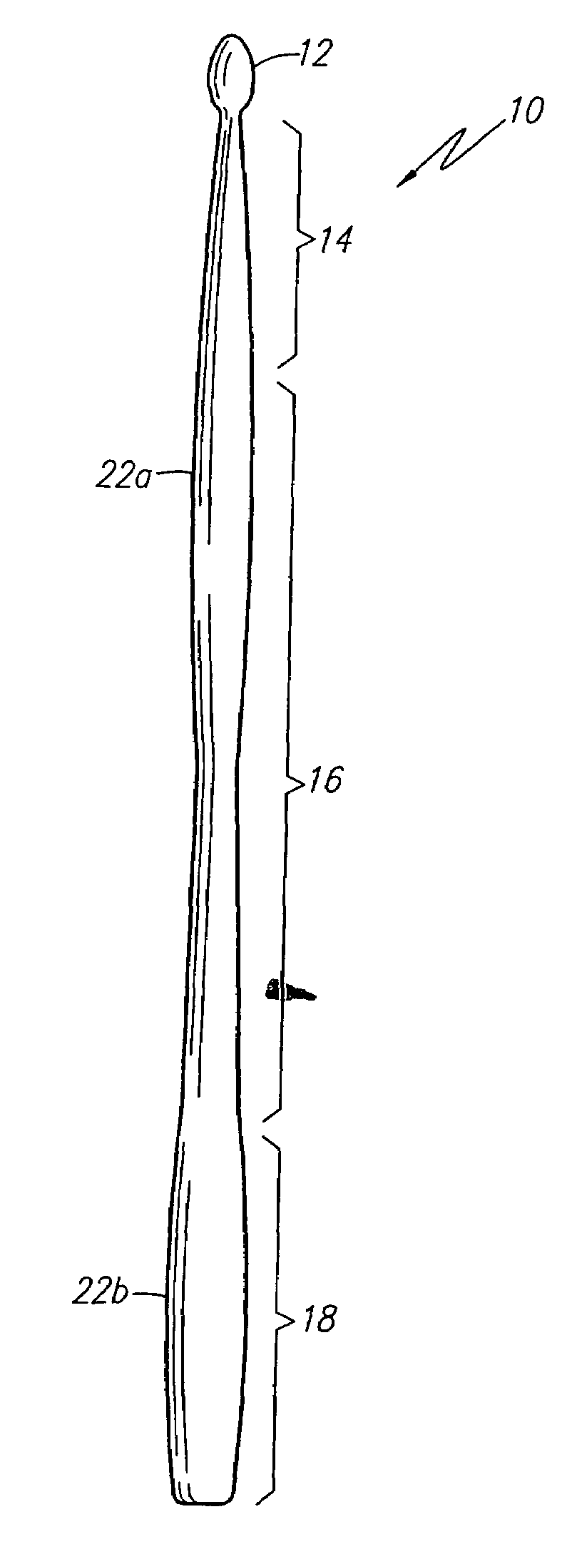
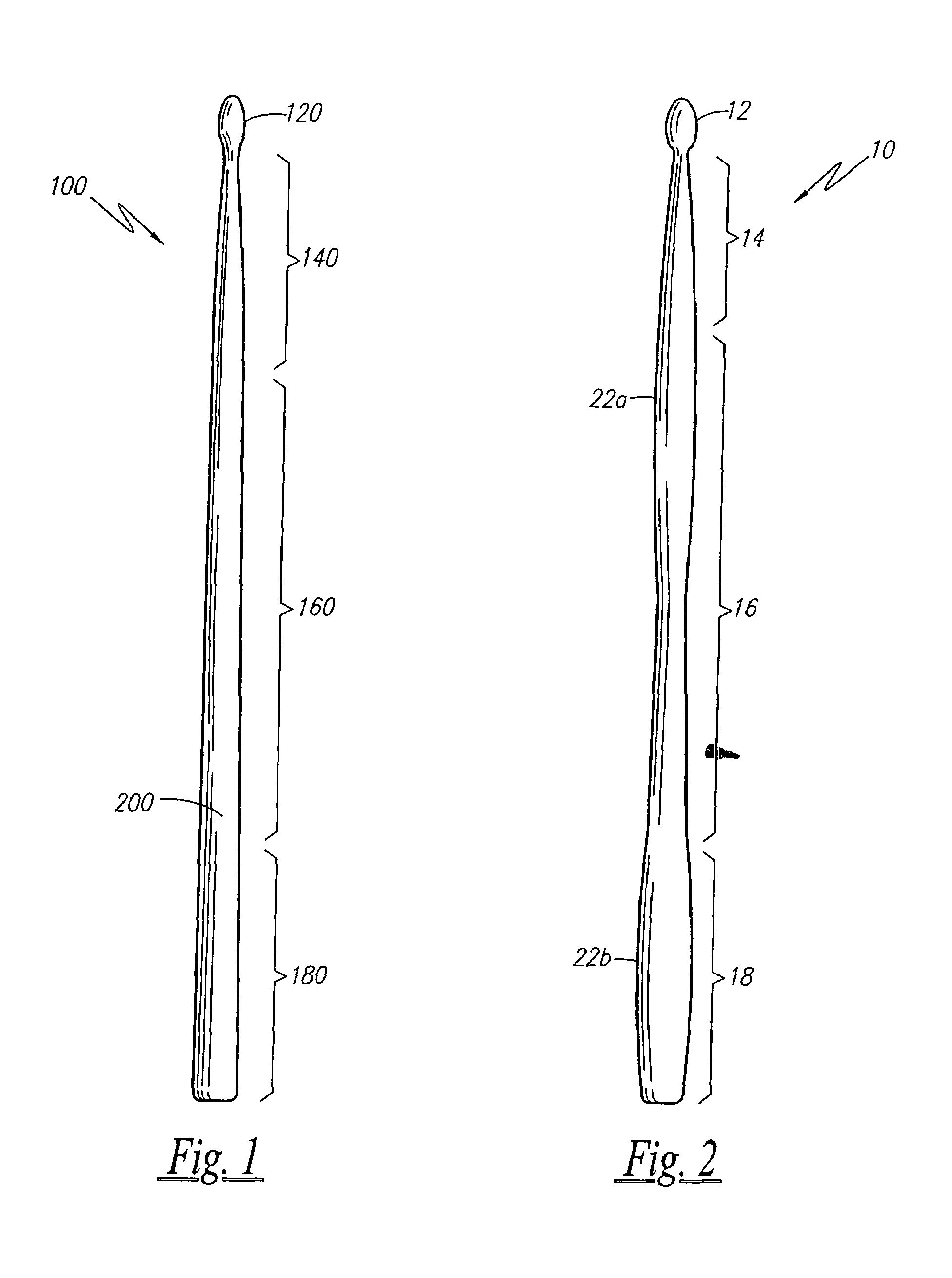
[0026]In order to describe the complete relationship of the improved invention to the prior art, it is essential that some description be given to the manner and to the practice of the functional utility of a conventional drum stick. A conventional drumstick 100 is shown in FIG. 1. Conventional drumsticks 100 comprise a tip 120, a shoulder 140, a shaft 160 and a butt 180. The tip 120 can be acorn shaped, barrel shaped, oval shaped or rounded. The tip 120 typically strikes the drumhead to produce a sound. The shoulder 140 is the portion of the length that tapers from the shaft 160 to the tip 120. The length of the shoulder 140 approximates one quarter (¼) the length of the drumstick 100. The shaft 160 is the cylindrical portion that travels across the greater part of the center length where the percussionist grips the drumstick 100. The shaft 160 ap...


PUM


Abstract

A solid drumstick tapers towards its balance point to redistribute weight at its shoulder and butt sections. A diameter of the shoulder and the butt portions increases or decreases in a consistent manner so as to not change the drumstick's balance point, but in a manner that still provides a means to move the mass outwards. A flared butt portion is less likely to cause slippage.

Description

RELATED APPLICATIONS[0001]There are no previously filed nor current co-pending applications anywhere in the world.BACKGROUND OF THE INVENTION[0002]1. Field of the Invention[0003]The present invention relates generally to a drumstick and, more specifically, to a drum stick that tapers towards its center point to provide a deeper, louder sound.[0004]2. Description of the Related Art[0005]It is well known that drums are constructed differently to produce and to compliment different types of music. Jazz musicians prefer a crisp, clean sound while rock musicians prefer a loud, deep sound. Typically, the drumhead, the tension of the drumhead, the diameter of the shell and the type of the shell all affect the pitch, the overtones and the sound rings produced by a drum.[0006]It would be more advantageous if a musician can produce a different sound by simply changing the drumstick. This would be especially advantageous for amateur drummers who cannot afford to purchase a variety of drumheads...

Claims


Application Information

Patent Timeline
IPC IPC(8): G10D13/02
CPCG10D13/003G10D13/12
Inventor JENDRISAK, MARK D.
Owner JENDRISAK MARK D
Why Eureka
Try Eureka