Optical module and optical communication device

a technology of optical communication device and optical module, which is applied in the direction of optical radiation measurement, instruments, semiconductor lasers, etc., can solve the problems of deteriorating waveform quality of optical signal at the time of high-speed modulation driving of light emitting elements, reducing the amount of light incident upon monitoring light receiving elements with an elevation of ambient temperature, etc., and achieves the effect of widening the operating temperature rang

Inactive Publication Date: 2008-10-21
SEIKO EPSON CORP
View PDF13 Cites 11 Cited by
  • Summary
  • Abstract
  • Description
  • Claims
  • Application Information

AI Technical Summary

Benefits of technology

[0009]In accordance with an advantage of some aspects of the invention, there can be provided optical modules whose operational temperature range can be widened without complicating their structure.

Problems solved by technology

However, even when the temperature characteristics of the respective member are suppressed, the emission angle of emission light of the VCSEL changes according to the ambient temperature, which causes a phenomenon in which the amount of light incident upon the monitoring light receiving element reduces with an elevation of the ambient temperature.
However, such a measure has a limitation due to restrictions on mounting, and is contradictory to the demand for miniaturization of optical modules.
However, when the light output is set to a relatively low level, the waveform quality of optical signal at the time of high-speed modulation driving of the light emitting element may be deteriorated.
This problem becomes more conspicuous as the ambient temperature lowers.
In other words, the operational temperature range of the optical module cannot be widened.
However, the element structure may require a complex design in order to improve the temperature characteristic of a light emitting element and to realize high-speed modulation.
However, such a method causes problems, such as, an increased number of components of the optical module, violation of the demand for miniaturization of the optical module, and the like.

Method used


Image

  • Optical module and optical communication device
  • Optical module and optical communication device
  • Optical module and optical communication device

Examples


embodiment 1

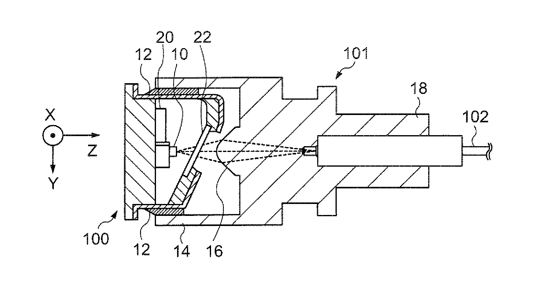
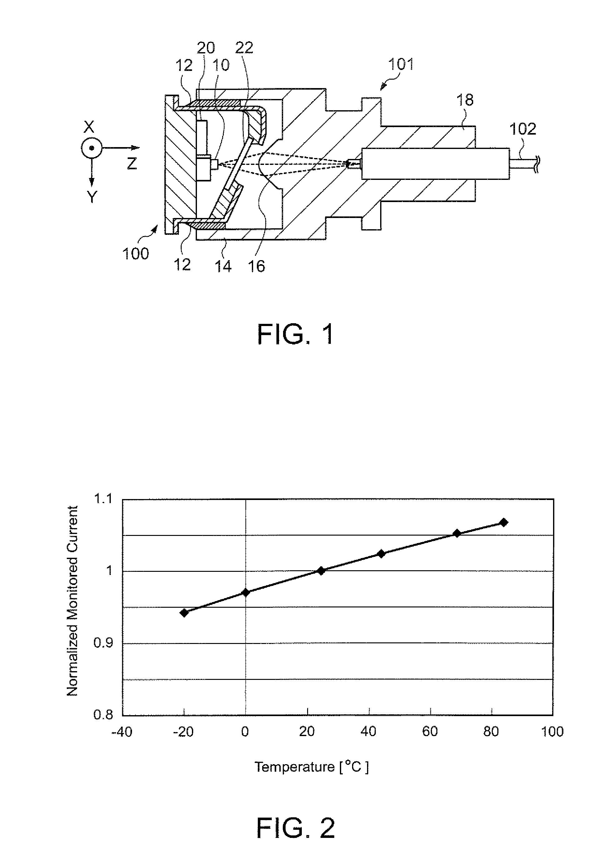
[0054]FIG. 1 is a cross-sectional view for describing the structure of an optical module in accordance with an embodiment of the invention. The optical module of the present embodiment is formed from a can package 100 and a connector part 101 positioned with each other, which are affixed with each other with an adhesive 12. The connector part 101 supports one end of an optical fiber 102, and optically couples the optical fiber 102 to a light emitting element 10 within the can package 100.

[0055]The can package 100 is formed from a housing made of metal or the like that packages the light emitting element 10. In the present embodiment, as the light emitting element 10, a VCSEL (vertical cavity surface emitting laser) diode that emits light in multimode is considered. The light emitting element 10 emits light with a wavelength of, for example, 850 nm. Also, the can package 100 is equipped with a monitoring light receiving element 20 as a system for monitoring light output of the light ...

embodiment 2

[0068]An optical module in accordance with Embodiment 2 is similar to Embodiment 1 (FIG. 1). More specifically, the optical module of the present embodiment is formed from a can package 100 and a connector part 101 positioned with each other, which are affixed with each other by using an adhesive 12. The connector part 101 supports one end of an optical fiber 102, and optically couples the optical fiber 102 to a light emitting element 10 within the can package 100.

[0069]The can package 100 is formed from a housing made of metal or the like that packages the light emitting element 10. In the present embodiment, as the light emitting element 10, a VCSEL that emits light in multimode is considered. The light emitting element 10 emits light with a wavelength of, for example, 850 nm. Also, the can package 100 is equipped with a monitoring light receiving element 20 as a system for monitoring light output of the light emitting element 10 and a semitransparent glass plate (semitransparent ...

embodiment 3

[0078]Next, an optical module in accordance with Embodiment 3 is described. The structure of the optical module in accordance with the present embodiment is generally the same as that of Embodiment 2 described above (see FIG. 1), and its illustration is therefore omitted. However, temperature characteristics of the monitoring light receiving element 20 and the semitransparent glass plate 22 are different from those of Embodiment 1, respectively. Their details are described below.

[0079]FIG. 12 is a graph showing one example of transmittance characteristic of the semitransparent glass plate in accordance with the present embodiment. In FIG. 12, temperatures (° C.) are indicated along the axis of abscissas, and transmittances T of the semitransparent glass plate 22 are indicated along the axis of ordinate. As shown in FIG. 12, the semitransparent glass plate 22 of the present embodiment has a characteristic in which its transmittance T increases (reflectivity decreases) with an increas...


PUM


Abstract

An optical module includes a light emitting element, a connector part that supports one end of an optical fiber and optically couples the optical fiber to the light emitting element, and a monitoring light receiving element that has a characteristic to increase photosensitivity with an increase in an ambient temperature, and receives a part of components of light emitted from the light emitting element.

Description

[0001]The entire disclosure of Japanese Patent Application Nos. 2005-331985, filed Nov. 16, 2005, 2005-331989, filed Nov. 16, 2005 and 2006-170463, filed Jun. 20, 2006 are expressly incorporated by reference herein.BACKGROUND[0002]1. Technical Field[0003]The present invention relates to optical modules and optical communications devices that are used for optical communications.[0004]2. Related Art[0005]A variety of modes of optical modules are known. One of them is an optical module having a structure in which a part of light emitted from a light emitting element is received by a monitoring light receiving element, thereby monitoring the amount of the light. This type of optical module performs feedback control of a driving current for the optical element based on a current outputted from the monitoring light receiving element according to the amount of received light, which makes it possible to maintain the amount of light emitted from the light emitting element constant without re...

Claims


Application Information

Patent Timeline
Patent Type & Authority Patents(United States)
IPC IPC(8): H01L31/14H04B10/12G02B6/42
CPCG01J1/02G01J1/0204G01J1/04G01J1/0411G01J1/0414G01J1/0451G01J1/32G02B6/4206H01S5/06804H01S5/0683H01S5/02252H01S5/02284H01S5/02296H01S5/02257H01S5/02326H01S5/02251
Inventor KITO, SATOSHIMIYAMAE, AKIRANAGASAKA, KIMIO
Owner SEIKO EPSON CORP
Why Eureka
Try Eureka