Rotary piezoelectric microactuator with an optimum suspension arrangement

a piezoelectric microactuator and suspension arrangement technology, applied in the direction of maintaining the head carrier alignment, recording information storage, instruments, etc., can solve the problems of inability to precisely control the head displacement with high efficiency, and it is difficult for actuators and servo systems to position the sld over the desired track quickly and accurately, so as to achieve high resonance frequency and high lateral displacement

Inactive Publication Date: 2008-10-21
SAE MAGNETICS (HK) LTD
View PDF17 Cites 2 Cited by
  • Summary
  • Abstract
  • Description
  • Claims
  • Application Information

AI Technical Summary

Benefits of technology

[0011]Another object of the present invention is to provide a new kind of suspension arrangement for suspension type design with this kind of microactuator, with a high lateral displacement and a high resonance frequency.
[0012]The microactuator of an embodiment in accordance with the present invention includes two active arms, each including a circular part and a straight part, with a symmetrical arrangement with one or more layers of piezoelectric materials in the structure. They are built in one body with connection by two parts, called connection bodies, at the two ends of the two arms respectively. The two active arms are connected to the two electric pads. When certain voltages of opposite polarities are applied to the two pads, one arm contracts while the other extends in their length direction. If one connection body is fixed as a fixed end, it will produce a moment and cause a rotary movement on the circular part of the arms and a deflection on the straight part of the arms so that the other connection body, as a free end, will get a big deflection along a tracking axis.

Problems solved by technology

However, this mechanism is unable to precisely control the displacement of the head with a high efficiency.
Since the disk storage capacity is increasing all of the time, it becomes more difficult for the actuator and servo system to position the SLD over the desired track quickly and accurately.

Method used


Image

  • Rotary piezoelectric microactuator with an optimum suspension arrangement
  • Rotary piezoelectric microactuator with an optimum suspension arrangement
  • Rotary piezoelectric microactuator with an optimum suspension arrangement

Examples


Embodiment Construction

[0024]Below the microactuator and disk drive suspension according to the present invention will be explained in more detail with reference to the illustrated embodiments.

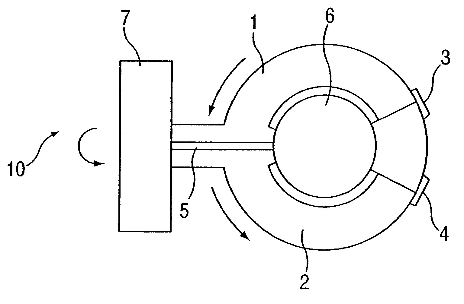
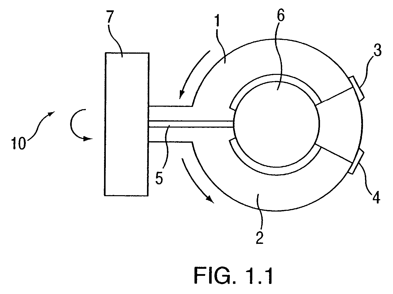
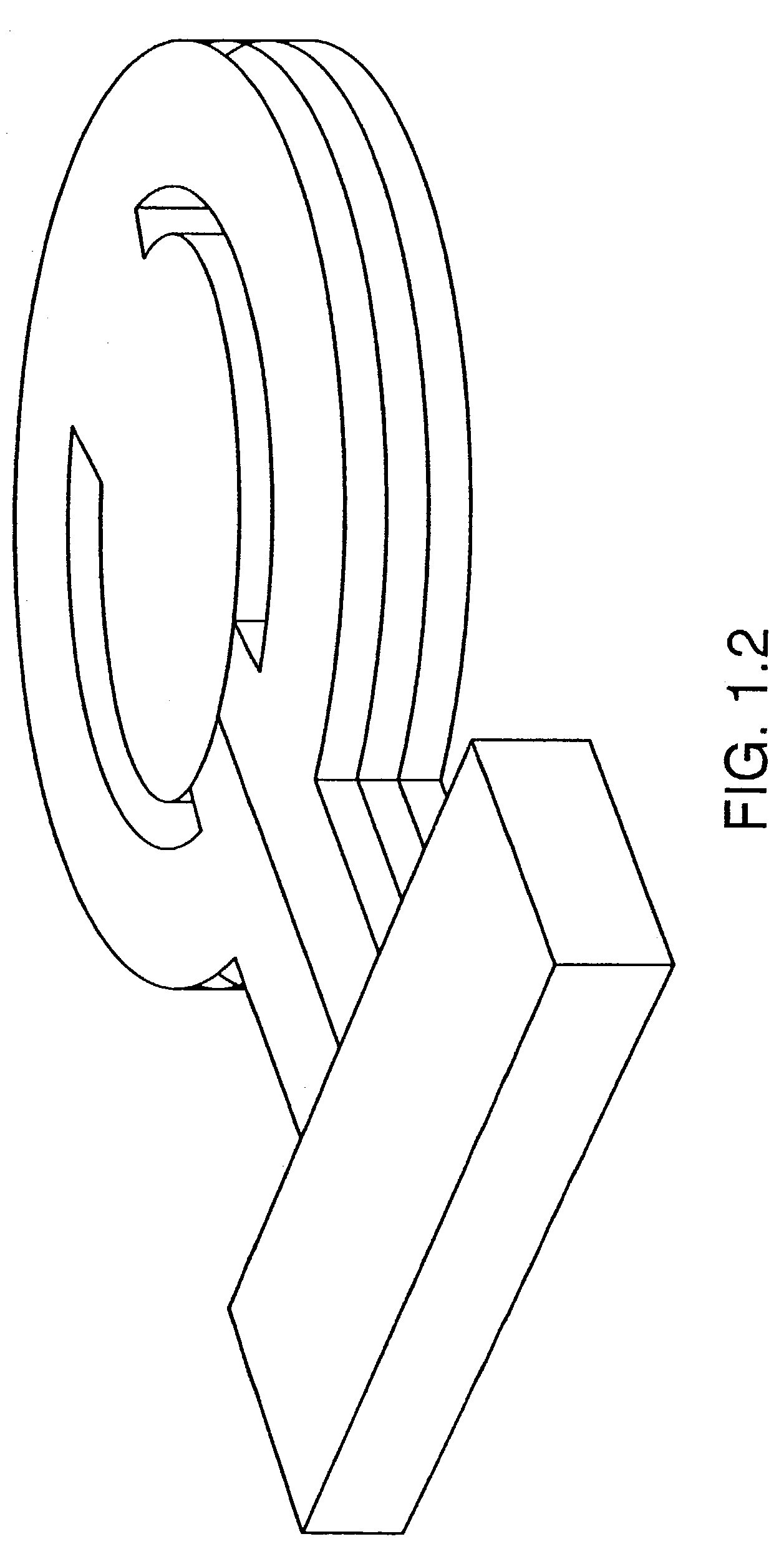
[0025]The basic structure of an embodiment of the rotary microactuator in accordance with the present invention is shown in FIG. 1.1. There are two active arms 1 and 2 which are formed of piezoelectric materials and built in such a way that they include two parts: annular parts and straight parts with a symmetry arrangement about a center line. Arms 1 and 2 are bonded together by two connection bodies 6 and 7 at their two ends respectively, but still in insulation from each other in structure. Numeral 5 is the insulation layer between the two straight arms. There are two electric pads 3 and 4, which are connected to arms 1 and 2 respectively. If the connection body 6 is chosen as a fixed end, the body 7 will be a free end. When a certain voltage is applied to the pads 3 and 4 in opposite polarities, one arm will ext...


PUM

PropertyMeasurementUnit
thicknessaaaaaaaaaa
displacementaaaaaaaaaa
voltageaaaaaaaaaa

Abstract

The invention relates to a microactuator comprising a movable structure having a symmetric axis about which the movable structure are divided into two parts which can produce the same movement but in opposite directions; two active arms built with piezoelectric material; two stationary structures to connect the two active arms at their two ends, respectively. The invention also relates to a disk drive suspension which is incorporated with the microactuator.

Description

RELATED APPLICATION[0001]This application is a Divisional of Patent Application Ser. No. 09 / 811,113, filed on Mar. 16, 2001, now U.S. Pat. No. 6,633,458.BACKGROUND OF THE INVENTION[0002]1. Field of the Invention[0003]The present invention relates to the field of disk drives, and in particular, to a microactuator for finely positioning a read / write head of a hard disk drive and a suspension arrangement of the hard disk with the microactuator.[0004]2. Description of the Related Art[0005]A disk drive is an information storage device that uses a rotatable disk with data tracks, a magnetic head (SLD [slider]) for reading or writing data from or onto the tracks, and an actuator connected to a carrier for moving the head across the disk. A servo system receives prerecorded positioning information read from the disk by the head, and sends control signals to the actuator to move the head to the desired track and keep following it when the head is flying.[0006]The SLD flying over information ...

Claims


Application Information

Patent Timeline
Patent Type & Authority Patents(United States)
IPC IPC(8): G11B21/02G11B21/24G11B5/58G11B5/55G11B5/56G11B5/596
CPCG11B5/5552
Inventor WU, KAIKASAJIMA, TAMONSHIRAISHI, MASASHISHANG, PING
Owner SAE MAGNETICS (HK) LTD
Why Eureka
Try Eureka