
Hierarchical netlist comparison by relevant circuit order

a technology of hierarchy and circuit order, applied in the field of hierarchy netlist comparison by relevant circuit order, can solve the problems of much higher complexity of the design today than that prepared, and achieve the effects of speeding up the debugging process, facilitating design debugging, and high complexity

Inactive Publication Date: 2008-10-21
VERIC SYST
View PDF17 Cites 4 Cited by
  • Summary
  • Abstract
  • Description
  • Claims
  • Application Information

AI Technical Summary

Benefits of technology

[0025]Designs prepared today are of much higher complexity than those prepared just a few years ago. Nowadays, with System-On-Chip (SOC) comprising of millions of transistors and many thousands of subcircuits, it has become necessary to build up the hierarchical designs such that subcircuits with the same name in both schematic and layout also has the same port names. Modern tools such as automated Place / Route and semi automatic placement tools like Cadence Virtuoso-XL, all ensure the port names are the same between a layout and a schematic. This also greatly facilitates debugging of the design in the extraction phase, where unwanted so-called parasitic components influence the circuit performance.
[0030](d) There is no need to keep track of subcircuit port name maps.
[0031]Modern layout proceeds using a bottom-up strategy where the lowest order subcircuits that contain no other subcircuits are made first. This is necessary since before building the higher levels of the design the size and port locations of the lower hierarchical designs must be known. Thus, as the layout proceeds it is generally the subcircuit at the highest hierarchy level that has not been verified while its constituting subcircuits have already been built and verified for logical interconnect.
[0032]This invention greatly speeds up the debugging process by verifying the logical interconnect of the most relevant circuit first. This way, the user can debug those circuits while the less relevant circuits are being verified. With the old bottom-up approach there is a lengthy wait for all subcircuits to be verified before starting on the top-level. In most cases these subcircuits are already likely to be logically equivalent since they have been built and verified at an earlier stage, and the confirmation is of less interest.
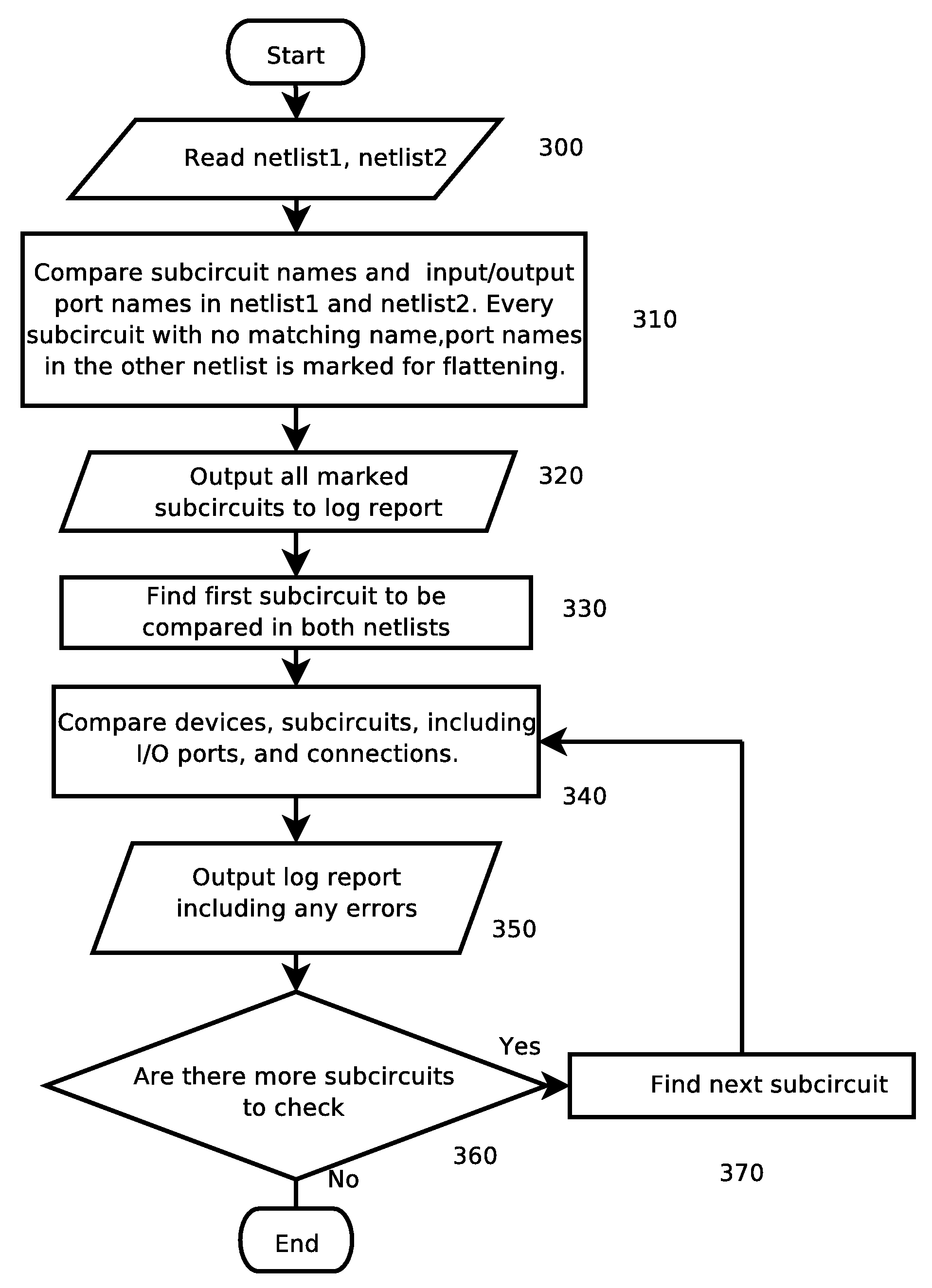
[0033]An invention is presented which compares two netlists hierarchically. A greater efficiency compared to earlier methods is achieved by taking advantage of the modern way of ensuring the port names of all subcircuits are identical between schematic / layout. The order with which the subcircuits are verified can then be defined arbitrarily and the most relevant subcircuits can be verified immediately, avoiding lengthy wait for less relevant subcircuits to be verified.
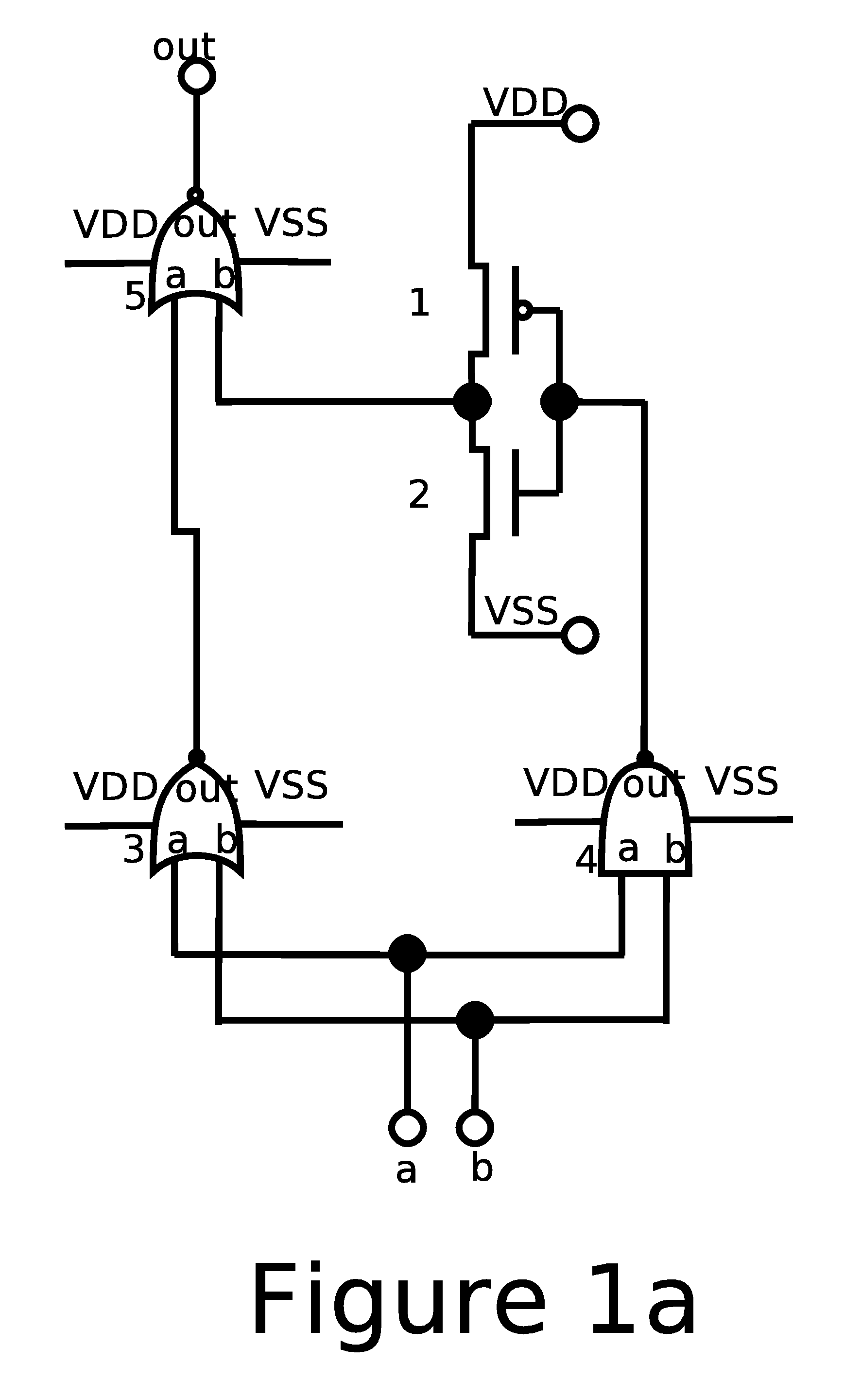
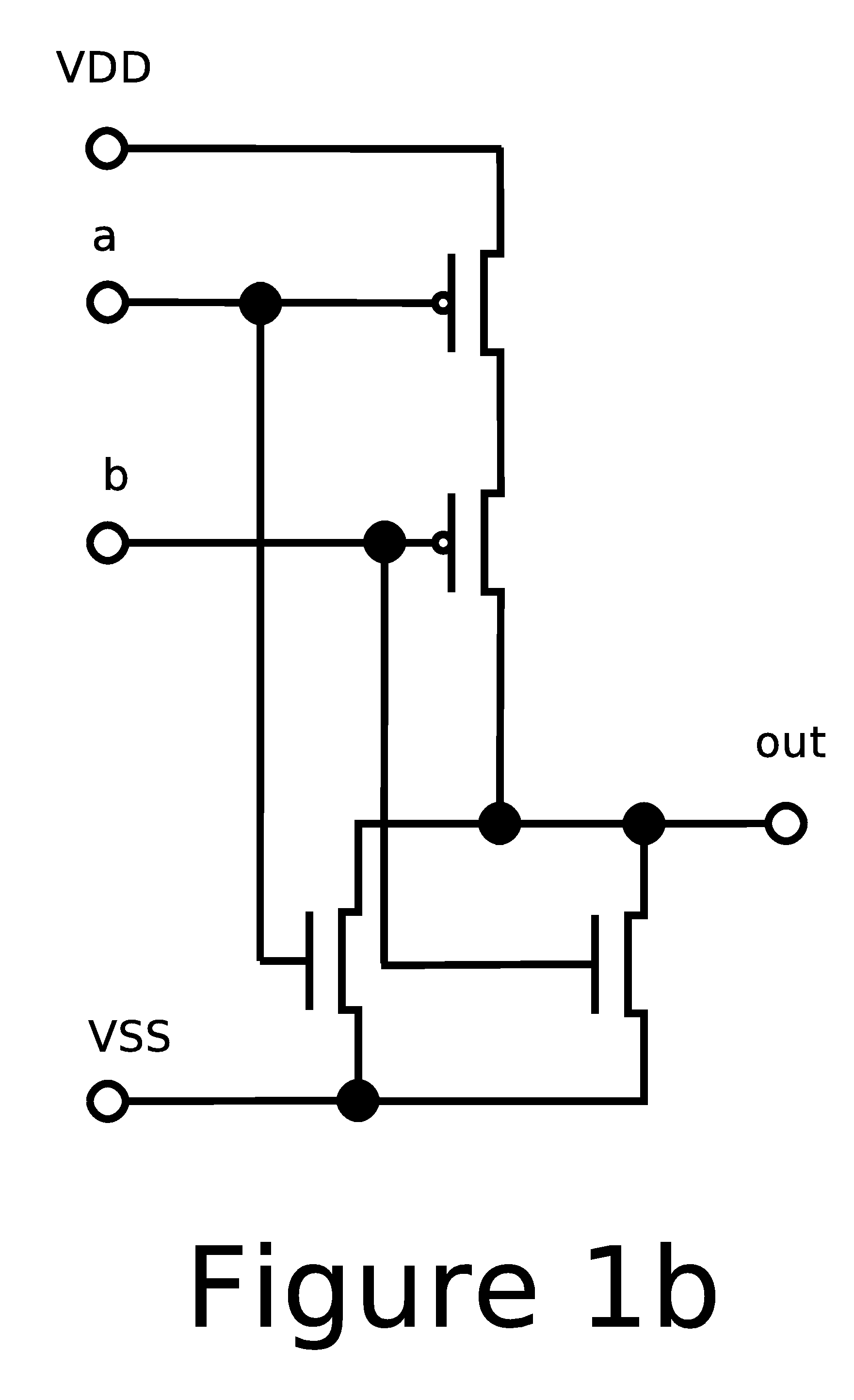
[0034]FIGS. 1a-c. shows a schematic design.

Problems solved by technology

Designs prepared today are of much higher complexity than those prepared just a few years ago.

Method used


Image

  • Hierarchical netlist comparison by relevant circuit order
  • Hierarchical netlist comparison by relevant circuit order
  • Hierarchical netlist comparison by relevant circuit order

Examples


Embodiment Construction

General System Configuration

[0047]A typical computer system used to implement the process described herein can be found in FIG. 4. It consists of a computer core 400 and peripheral units 404, 405, and 406. The computer core itself 400 is made up of a central processing unit (CPU) 401, an input / output circuit 402 to handle communication between all parts of the computer system, and a memory 403 for storing intermediate computational results. All these elements are intended to be representative of a broad category of data processors, such as Personal Computers (PC's), mini computers and super computers to name a few.

[0048]The peripheral unit 404 is intended to represent an input device, here depicted as a keyboard connected to the computer cores input / output circuit. It can, of course, be anything from a keyboard and cursor control (mouse) to magnetic devices such as hard drives / tape drives and other such well-known devices. The peripheral unit 405 is intended to represent external ma...


PUM


Abstract

The present invention uses the strength of modern hierarchical integrated circuit design to speed up the comparison of two netlists. Instead of working from bottom-up it can proceed with arbitrary hierarchical order to do the comparison. This has the advantage that the subcircuits that are most interesting can be verified first and avoids the long wait to go through the hierarchy.

Description

CROSS-REFERENCE TO RELATED APPLICATIONS[0001]Not ApplicableFEDERALLY SPONSORED RESEARCH[0002]Not ApplicableSEQUENCE LISTING OR PROGRAM[0003]Not ApplicableBACKGROUND OF THE INNOVATION[0004]1. Field of Invention[0005]The present invention relates to the field of verifying two or more designs of circuits to determine if the devices and interconnections found in one design appear in the same way in the other designs.[0006]2. Prior Art[0007]When designing an electric circuit it is customary to start with an abstract logic design called a schematic. This will identify the logic components and interconnects necessary to provide the desired functionality. An example of this can be found in FIG. 1a, where five logic components, 1, 2, 3, 4, 5, two input ports, a, b, one output port out, power supply VDD and ground connection VSS are shown. The interconnects between the components and between the components and the ports are represented with the wires in FIG. 1a. To avoid too much clutter the ...

Claims


Application Information

Patent Timeline
Patent Type & Authority Patents(United States)
IPC IPC(8): G06F17/50
CPCG06F17/5081G06F30/398
Inventor SAHRLING, MIKAEL
Owner VERIC SYST
Learn More