Method of modulating printhead peak power requirement using out-of-phase firing

a printhead and peak power technology, applied in printing, inking apparatus, other printing apparatus, etc., can solve the problems of inability to meet current demands, inability to print pages, fluctuation of printhead power requirement during printing of pages, etc., to achieve simplified design and manufacture of printhead power supply, the effect of reducing the degree of peak power fluctuation within each line-time and ensuring the quality of printing

Active Publication Date: 2008-10-28
SILVERBROOK RES PTY LTD +1
View PDF7 Cites 9 Cited by
  • Summary
  • Abstract
  • Description
  • Claims
  • Application Information

AI Technical Summary

Benefits of technology

[0048]All aspects of the invention provide the advantage of modulating a peak power requirement of the inkjet printhead. The corollary is that a power supply, which supplies power to the printhead, need not be specially adapted to supply severely fluctuating amounts of power throughout each print cycle. In the present invention, the degree of peak power fluctuations within each line-time are substantially reduced. Hence, the design and manufacture of the printhead power supply may be simplified and the power supply is made more robust by virtue of not having to deliver severely fluctuating amounts of power to the printhead.
[0049]In addition to modulating the peak power requirement of the printhead, the present invention allows print quality to be improved by using redundant nozzle rows, and without compromising the above-mentioned improvements in peak power requirement. Print quality may be improved by, for example, reducing the visual effects of unknown dead nozzles in the printhead, and reducing the visual effects of misdirected ink droplets.
[0056]Optionally, the printhead comprises a plurality of transversely aligned color channels, each color channel comprising at least one nozzle row extending longitudinally along the printhead, each nozzle in a color channel ejecting the same colored ink. As described in more detail below, each transversely aligned color channel is allotted a portion of a line-time for firing. In this way, dot-on-dot printing can be achieved, which is optimal for dithering.
[0058]Each color channel may comprise a plurality of nozzle rows. Optionally, each color channel comprises a pair of nozzle rows. Typically, nozzle rows in the same color channel are transversely offset from each other. For example, one nozzle row in a pair may be configured to print even dots on a line, while the other nozzle row in the pair may be configured to print odd dots on the same line. The nozzle rows in a pair are usually spaced apart in a transverse direction to allow convenient timing of nozzle firings. For example, the even and odd nozzle rows in one color channel may be spaced apart by two lines of printing.
[0061]Optionally, a visual effect of misdirected ink droplets is reduced. An advantage of using a plurality (e.g. two) nozzles for printing the same column is that misdirected ink droplets may be averaged out between those nozzles.
[0063]Optionally, a visual effect of malfunctioning or dead nozzles is reduced. The nozzles may be known dead nozzles or unknown dead nozzles. The visual effect of an unknown dead nozzle is reduced by virtue of the fact that the nozzle is only required to print about half of the time. For example, with an unknown dead magenta nozzle, a column of magenta dots would be missing completely with no redundancy, whereas half of the column is still printed using redundancy. The latter is, of course, far more visually acceptable than the former.

Problems solved by technology

Such printers are inherently slow and are becoming unable to meet the needs of current demands of inkjet printers.
In addition, the power requirement of the printhead during printing of the page may fluctuate.
Due to a particular configuration of the printhead or printer controller, some lines of print may consume more power than other lines of print.
As a consequence, each line of printing is typically not a perfectly straight line (unless the physical arrangements of the nozzles directly compensates for the firing order in which case it can be a straight line), although this imperfection is undetectable to the human eye.
For example, since yellow makes the lowest contribution (11%) to luminance, the human eye is least sensitive to missing yellow dots and, therefore, yellow would be a poor choice for a redundant color.
However, while the redundancy scheme described in U.S. Ser. No. 10 / 854,507, filed May 27, 2004 and U.S. Ser. No. 10 / 854,523, filed May 27, 2004 can compensate for dead nozzles and reduce (e.g. halve) the number of dots fired by some nozzles, it places increased demands on the power supply which is used to power the printhead.
(If all nozzle rows were to fire simultaneously, there would be an unacceptable current overload of the printhead).
From the standpoint of the power supply, this situation is optimal, but, on the other hand, there is no means for minimizing the visual effects of dead nozzles.
It is evident from the above table that the peak power requirement of the printhead fluctuates severely between 1.67x and 0 within the period of a line-time, even though the average power consumed over the whole line-time is still x. In practical terms, it is difficult to manufacture a power supply which is able to deliver severely fluctuating amounts of power within each line-time.
While this configuration would address peak power and misdirectionality issues, it would not address the problem of known dead nozzles, since only one of each redundant color channel would be able to be fired in a given line-time, thereby losing one of the major advantages of redundancy.

Method used


Image

  • Method of modulating printhead peak power requirement using out-of-phase firing
  • Method of modulating printhead peak power requirement using out-of-phase firing
  • Method of modulating printhead peak power requirement using out-of-phase firing

Examples


Embodiment Construction

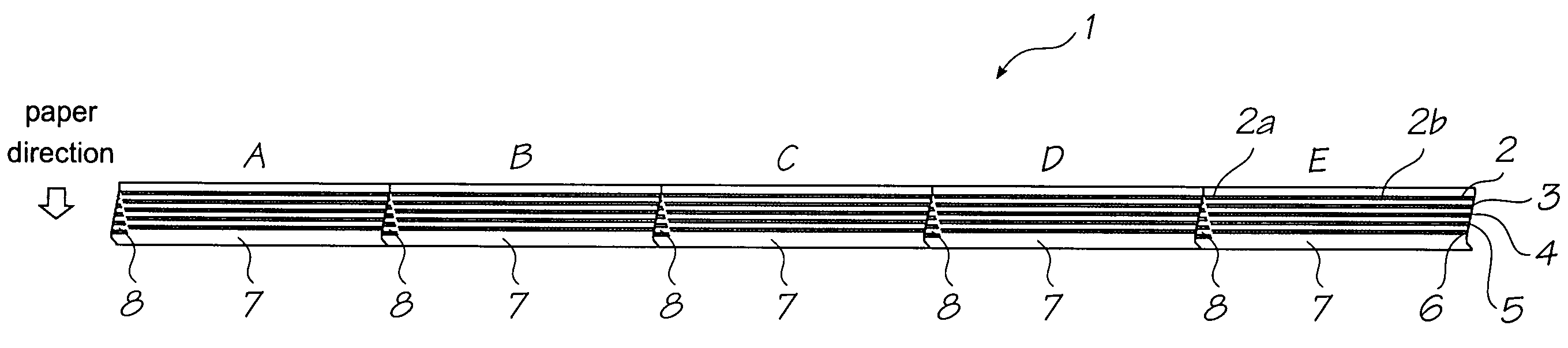
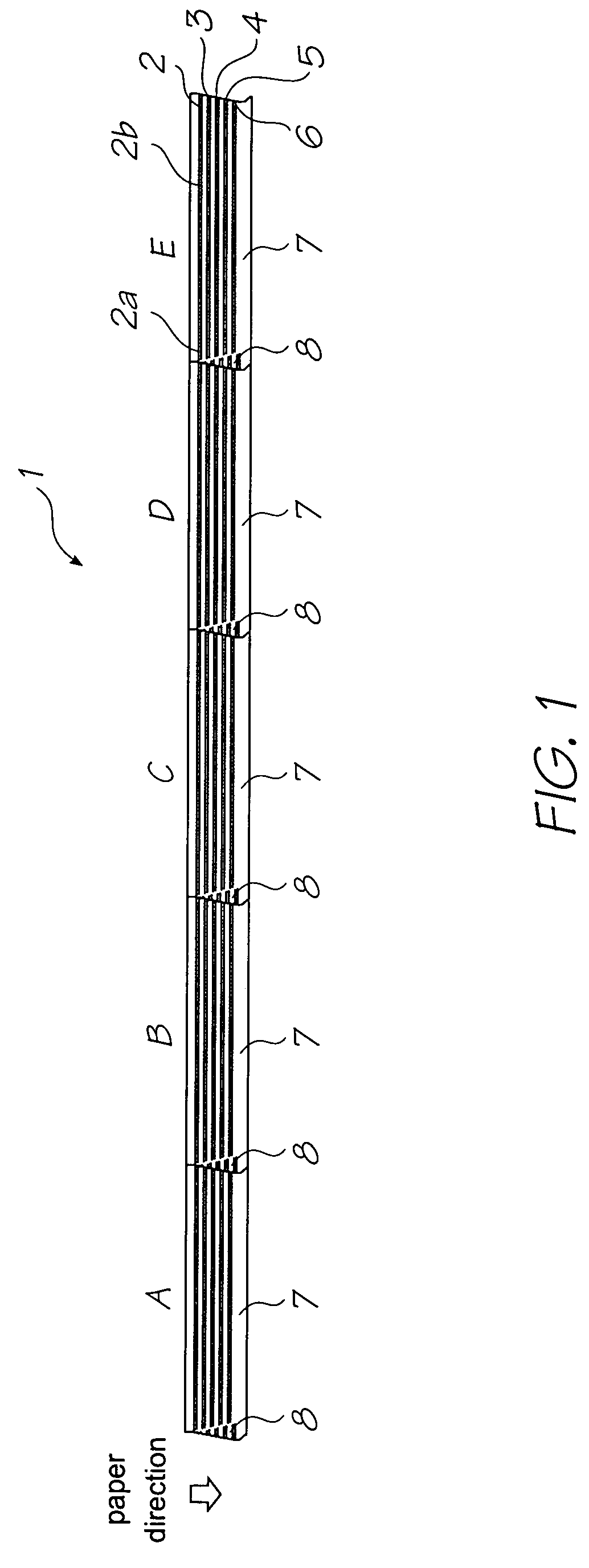
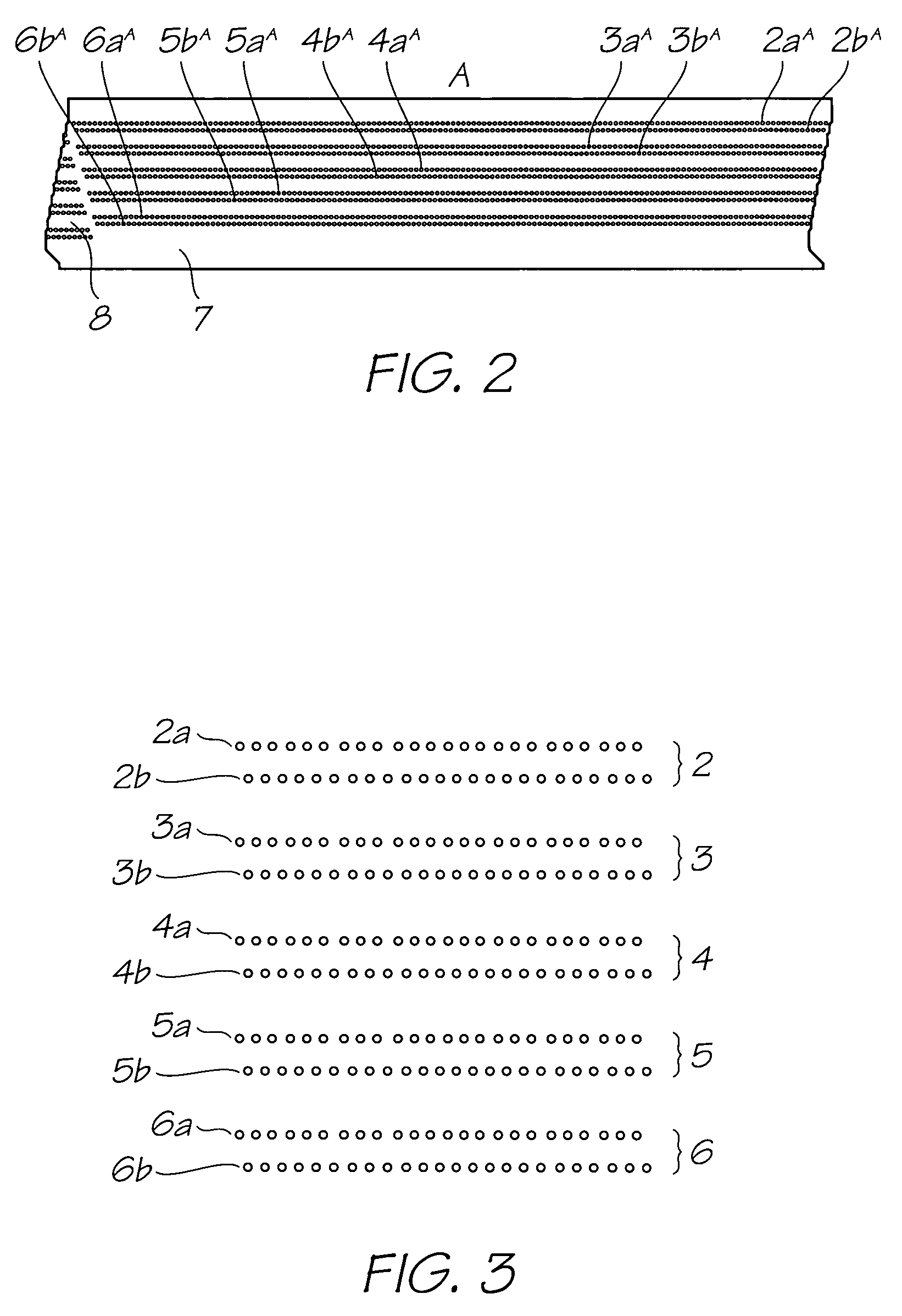
[0078]The invention will be described with reference to a CMY pagewidth inkjet printhead 1, as shown in FIG. 1. The printhead 1 has five color channels 2, 3, 4, 5 and 6, which are C1, C2, M1, M2 and Y respectively. In other words cyan and magenta have ‘redundant’color channels. The reason for making C and M redundant is that Y only contributes 11% of luminance, while C contributes 30% and M contributes 59%. Since the human eye is least sensitive to yellow, it is more visually acceptable to have missing yellow dots than missing cyan or magenta dots. In this printhead, black (K) printing is achieved via process-black (CMY).

[0079]The printhead 1 is comprised of five abutting printhead modules 7, which are referred to from left to right as A, B, C, D and E. The five modules 7 cooperate to form the printhead 1, which extends across the width of a page (not shown) to be printed. In this example, each module 7 has a length of about 20 mm so that the five abutting modules form a 4″ printhea...


PUM


Abstract

A method of modulating a peak power requirement of an inkjet printhead is provided. The printhead comprises a plurality of transversely aligned color channels, each color channel comprising at least one nozzle row extending longitudinally along said printhead. Each nozzle in a color channel ejects the same colored ink. The printhead is comprised of a plurality of printhead modules, each printhead module comprising a respective segment of each nozzle row. The method comprising each of the printhead modules firing a respective segment within a predetermined segment-time, wherein at least one of the fired segments is contained in a different color channel from at least one other of the fired segments.

Description

FIELD OF THE INVENTION[0001]This invention relates to a method of printing from an inkjet printhead, whilst modulating a peak power requirement for the printhead. It has been developed primarily to reduce the demands on a pagewidth printhead power supply, although other advantages of the methods of printing described herein will be apparent to the person skilled in the art.CO-PENDING APPLICATIONS[0002]The following applications have been filed by the Applicant simultaneously with the present application:[0003]11 / 29380011 / 29380211 / 29380111 / 29380811 / 29380911 / 29383211 / 29383811 / 29384111 / 29379911 / 29379611 / 29379711 / 29379811 / 29380411 / 29384011 / 29380311 / 29383311 / 29383411 / 29383511 / 29383611 / 29383711 / 29379211 / 29379411 / 29383911 / 29382611 / 29382911 / 29383011 / 29382711 / 293828727049411 / 29382311 / 29382411 / 29383111 / 29381511 / 29381911 / 29381811 / 29381711 / 29381611 / 29382011 / 29381311 / 29382211 / 293812735749611 / 29381411 / 29379311 / 29384211 / 29381111 / 29380711 / 29380611 / 29380511 / 293810[0004]The disclosures of these co-pe...

Claims


Application Information

Patent Timeline
Patent Type & Authority Patents(United States)
IPC IPC(8): B41J2/015B41J29/38
CPCB41J2/04515B41J2/0452B41J2/04586B41J2/155B41J2202/20
Inventor BROWN, BRIAN ROBERTWALMSLEY, SIMON ROBERTSILVERBROOK, KIA
Owner SILVERBROOK RES PTY LTD
Why Eureka
Try Eureka