
Satellite tracking antenna system and method therefor

a satellite and antenna technology, applied in the direction of antennas, direction finders, antenna adaptation in movable bodies, etc., can solve the problem of a more delicate control technique to always track a satellite that is required differently, and the directional direction of the reflector is not easy to be quickly compensated, and the error of the satellite signal level value with respect to the main lobe of the satellite signal

Active Publication Date: 2008-11-04
INTELLIAN TECH
View PDF12 Cites 9 Cited by
  • Summary
  • Abstract
  • Description
  • Claims
  • Application Information

AI Technical Summary

Benefits of technology

The present invention provides a satellite tracking antenna system and a satellite tracking method that can accurately track a satellite regardless of a sudden movement of a mobile body. By tilting the reflector or sub-reflector in a specific direction and averaging the sampled satellite signal level values, an azimuth or elevation error signal is generated to move the reflector or sub-reflector in the opposite direction to achieve precise tracking. Additionally, an absolute position measurement bar and a detection means can be installed at the sub-reflector to measure the rotation period in real time and compensate for the sampling period to more accurately track a satellite.

Problems solved by technology

Accordingly, a more delicate control technique to always track a satellite is required differently from a fixed satellite antenna.
Since the step tracking method has a long sampling period in which a satellite signal is sampled in a direction in which the reflector is tilted in order to compensate the directional direction of the reflector, it is not easy that the directional direction of the reflector is quickly compensated in response to rapid movements of a mobile body.
In this case, an error occurs in a satellite signal level value with respect to a main lobe of a satellite signal caused by movement of the mobile body.
Therefore, an error occurs in generating an error signal.
However, a satellite tracking antenna employing a conventional conical scan method has a technical problem to set a sampling period which is information of the amount of time for precisely sampling a satellite signal at each position in which a sub-reflector is tilted.
It is difficult to precisely track a satellite without frequently compensating the satellite signal sampling period.
As described above, according to a conventional satellite tracking antenna, since a satellite is tracked without compensating an error of a satellite tracking signal which may occur caused by the movement of a mobile body, a distorted result may be generated.
Also, since a satellite is tracked by sampling a satellite signal without properly compensating a satellite signal sampling period according to rotation period change of a sub-reflector, tracking satellite is not precisely performed.

Method used


Image

  • Satellite tracking antenna system and method therefor
  • Satellite tracking antenna system and method therefor
  • Satellite tracking antenna system and method therefor

Examples


first embodiment

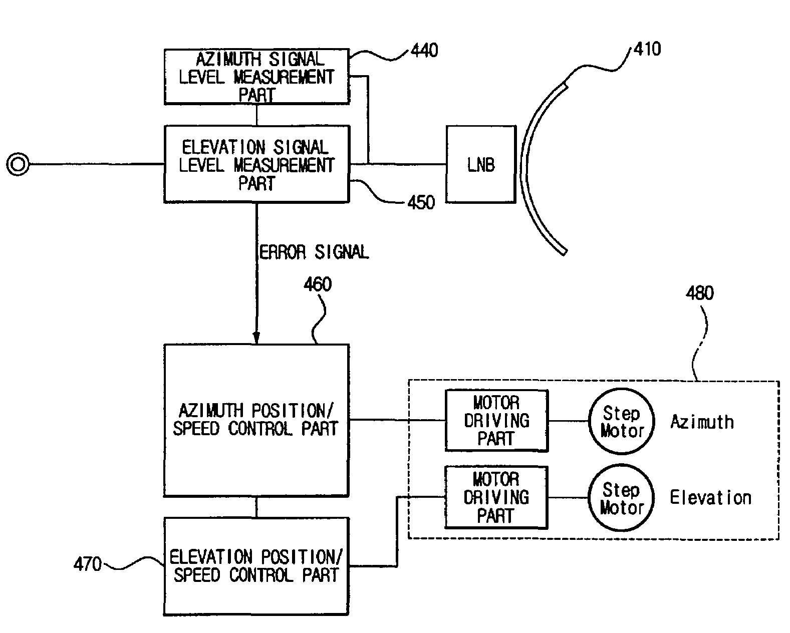
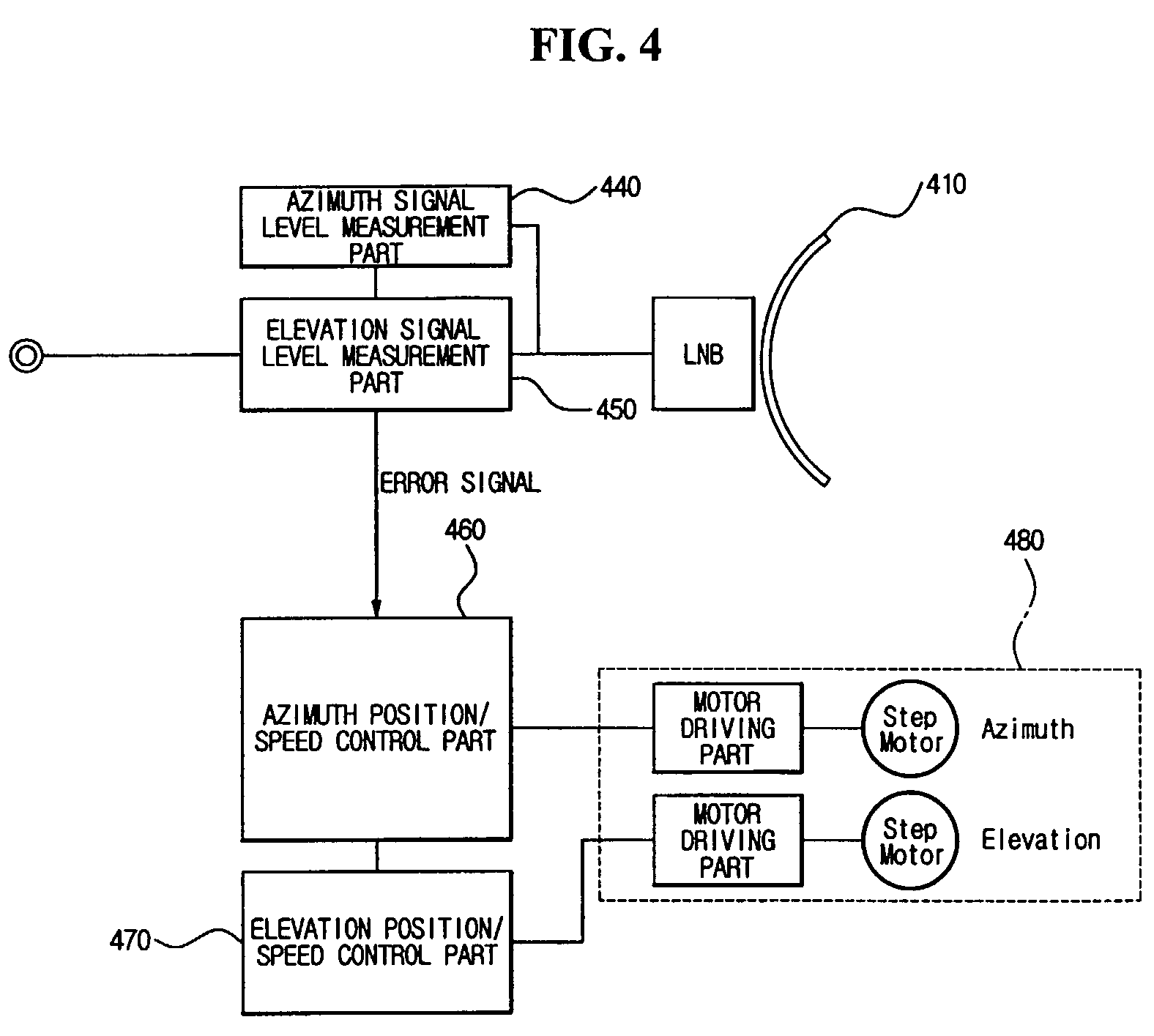
[0057]FIG. 4 is a block diagram illustrating a configuration of a satellite tracking antenna system according to the present invention.

[0058]The satellite tracking antenna system according to the first embodiment tilts a reflector in at least one specific direction to perform operation of tracking satellite signal, samples a satellite signal received in at least one position in which the reflector is tilted and disposed, generates an error signal by comparing sizes between the sampled satellite signals, and compensates a directional direction of the reflector such that the reflector is directed to a main lobe of the satellite signal.

[0059]The satellite tracking antenna system shown in FIG. 4 includes a reflector 410, an azimuth signal level measuring part 440, an elevation signal level measuring part 450, an azimuth position / speed control part 460, an elevation position / speed control part 470, and a reflector driving means 480.

[0060]The reflector 410 is directed to a satellite which...

second embodiment

[0116]FIG. 9 is a configuration diagram illustrating a configuration of a satellite tracking antenna system according to the present invention.

[0117]The satellite tracking antenna system according to the second embodiment of the present invention illustrated in FIG. 9 includes a reflector 910, a sub-reflector 920, a sub-reflector rotation part 930, an azimuth signal level measuring part 940, an elevation signal level measuring part 950, an azimuth position / speed control part 960, an elevation position / speed control part 970, and a reflector driving means 980.

[0118]The reflector 910 is directed to a predetermined satellite and receives a satellite signal from the satellite. The reflector 910 according to the second embodiment may not perform the operation of being tilted in at least one direction as the first embodiment described above.

[0119]The sub-reflector 920 is tilted in a predetermined azimuth or elevation direction, receives the satellite signal reflected by the reflector 910,...

third embodiment

[0155]FIG. 13 is a block diagram illustrating a configuration of a satellite tracking antenna system according to the present invention.

[0156]A conical scan tracking a satellite by rotating and tilting a sub-reflector can be applied to the satellite tracking antenna system according to the third embodiment, as the second embodiment. When the conical scan is realized, a rotation period of the sub-reflector may be changed according to aging, wear, etc. of a sub-reflector rotation part rotating the sub-reflector. The satellite tracking antenna system according to the third embodiment compensates a satellite signal sampling period in response to rotation period change of the sub-reflector.

[0157]As illustrated in FIG. 13, the satellite tracking antenna system includes a reflector 1310, a sub-reflector 1320, a sub-reflector rotation part 1330, a satellite signal sampling part 1340, a period control module 1350, an azimuth position / speed control part 1360, an elevation position / speed contr...


PUM


Abstract

The present invention relates to a satellite tracking antenna system and a satellite tracking method. Step tracking in which the size of a satellite signal sampled in at least one position in which a reflector of the satellite tracking antenna system is tilted is compared to track a satellite is performed, and a measured value of the satellite signal sampled in a specific position in which the reflector is tilted in N−1th tracking and a measured value of the satellite signal sampled in the specific position in which the reflector is tilted in Nth tracking are averaged to compute a value. The reflector is driven according to the value to track the satellite, thereby minimizing a satellite tracking error caused by a sudden movement of a mobile body equipped with the satellite tracking antenna system.

Description

TECHNICAL FIELD[0001]The present invention relates to a satellite tracking antenna system and a method of tracking satellites, and more particularly, to an antenna system and a method of tracking satellites, which can minimize satellite tracking error according to movements of a mobile body equipped with the satellite tracking antenna system. In operation of step tracking in which the size of satellite signal sampled in at least one specific position in which a reflector of the satellite tracking antenna system is tilted is compared to track the satellite, a measured value of a satellite signal sampled in a specific position in which the reflector is tilted in N−1th tracking and a measured value of a satellite signal sampled in the specific position in which the reflector is tilted in Nth tracking are averaged to drive the reflector according to the computed value.[0002]Also, the present invention relates to a satellite tracking antenna system which can precisely track a satellite. ...

Claims


Application Information

Patent Timeline
Patent Type & Authority Patents(United States)
IPC IPC(8): H01Q3/00G01S3/42G01S3/56H01Q1/27H01Q3/08H01Q3/20H01Q19/19
CPCG01S3/42G01S3/56H01Q1/27H01Q3/08H01Q3/20H01Q19/193
Inventor EOM, KWANG SIK
Owner INTELLIAN TECH
Learn More