Wide dynamic range operations for imaging

a wide dynamic range and image sensor technology, applied in the field of electromagnetic conductor devices, can solve the problems of image distortion, limited dynamic range on the upper end, and the methods disclosed by yadid-pecht are not well suited to color imaging

Active Publication Date: 2008-11-04
MICRON TECH INC
View PDF16 Cites 76 Cited by
  • Summary
  • Abstract
  • Description
  • Claims
  • Application Information

AI Technical Summary

Problems solved by technology

Dynamic range is limited on an upper end by the charge saturation level of the sensor, and on a lower end by noise imposed limitations and / or quantization limits of the analog to digital converter used to produce the digital image.
When the dynamic range of an image sensor is too small to accommodate the variations in light intensities of the imaged scene, image distortion occurs.
Additionally, the methods disclosed by Yadid-Pecht are not well suited to color imaging.
Thus, the method of Wandell requires additional circuitry and cannot be implemented using conventional CMOS image sensor circuits, which is undesirable.
Because each pixel cell integrates charge for two time periods per frame, additional sample and hold circuitry is required, which is undesirable.

Method used


Image

  • Wide dynamic range operations for imaging
  • Wide dynamic range operations for imaging
  • Wide dynamic range operations for imaging

Examples


Embodiment Construction

[0038]In the following detailed description, reference is made to the accompanying drawings, which form a part hereof and illustrate specific embodiments in which the invention may be practiced. In the drawings, like reference numerals describe substantially similar components throughout the several views. These embodiments are described in sufficient detail to enable those skilled in the art to practice the invention, and it is to be understood that other embodiments may be utilized, and that structural, logical and electrical changes may be made without departing from the spirit and scope of the present invention.

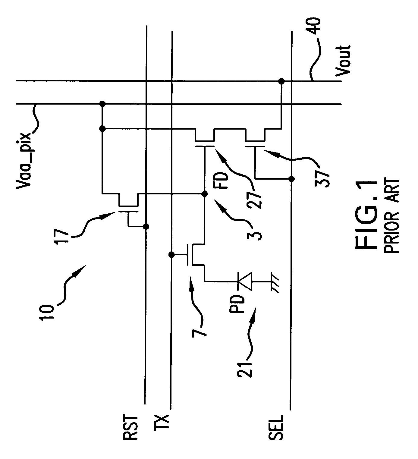
[0039]The term “pixel” or “pixel cell” refers to a picture element unit cell containing a photo-conversion device and associated transistors or other circuitry that convert electromagnetic radiation to an electrical signal. For purposes of illustration, representative pixel cells are illustrated in the figures and description herein, and typically all pixels in an image s...


PUM


Abstract

Embodiments provide a method and apparatus that achieve wide dynamic range operation of an image sensor. In an array of pixel cells, first charge is accumulated in a first subset of pixel cells during a first integration period and second charge is accumulated in a second subset of pixel cells during a second integration period. A length of the first integration period is different than a length of the second integration period, and the first and second charge are accumulated during a same frame and are read out.

Description

FIELD OF THE INVENTION[0001]The present invention relates to the field of semiconductor devices, particularly to the operation of an image sensor to achieve improved dynamic range.BACKGROUND OF THE INVENTION[0002]Complimentary Metal Oxide Semiconductor (CMOS) Active Pixel Sensors (APS) are increasingly being used as a lower cost alternative to Charge Coupled Devices (CCDs). A CMOS image sensor circuit includes a focal plane array of pixel cells, each one of the cells includes a photo-conversion device, such as a photogate, photoconductor, or photodiode, for accumulating photo-generated charge. Each pixel cell may include a transistor for transferring charge from the photo-conversion device to a sensing node, and a transistor, for resetting a sensing node to a predetermined charge level prior to charge transfer. The pixel cell may also include a source follower transistor for receiving and amplifying charge from the sensing node and an access transistor for controlling the readout of...

Claims


Application Information

Patent Timeline
Patent Type & Authority Patents(United States)
IPC IPC(8): H04N5/235G03B7/00H04N3/14H04N5/347H04N5/353H04N5/355H04N5/374H04N9/04H04N9/083
CPCH04N5/2355H04N5/35554H04N9/045H04N23/741H04N25/583H04N25/70H04N23/843H04N25/134
Inventor ANDO, HARUHISANAKAMURA, JUNICHI
Owner MICRON TECH INC
Why Eureka
Try Eureka