Mandible positioning devices

a technology for mandibles and devices, applied in non-surgical orthopedic devices, medical science, dentistry, etc., can solve the problems of not being accessible, not allowing the spacing between upper and lower bite blocks to be adjusted, and awakening patients by the consequent lack of oxygen and blood

Active Publication Date: 2008-11-11
HALSTROM LEONARD W
View PDF12 Cites 23 Cited by
  • Summary
  • Abstract
  • Description
  • Claims
  • Application Information

AI Technical Summary

Benefits of technology

[0011]It is accordingly an object of the present invention to provide a novel and improved mandible positioning device having upper and lower bite blocks which can be manually adjusted in position relative to one another while the device is installed in the mouth of a patient.
[0012]It is a further object of the present invention to provide a manually adjustable mandible positioning device which allows a lower bite block to be adjusted forwardly relative to an upper bite block and which also allows the vertical spacing between the upper and lower bite blocks to be adjusted.
[0014]Consequently, when the present mandible positioning device is in use, the position of the lower bite block can be adjusted, for example in a clinical setting while the patient is awake and in order to allow visual inspection of the patient's airway, e.g. to determine the optimum relative positions of the upper and lower bite blocks to counteract snoring. By locating the manually adjustable connection forwardly of the upper and lower bite blocks, the space between the upper and lower bite blocks, within the patient's mouth, can be left unobstructed by these members, which facilitates such visual inspection.

Problems solved by technology

When this occurs, the patients are awakened by the consequent lack of oxygen and blood, which often occurs with a loud snort or a bodily jerk.
It is, however, a disadvantage of this prior device that the connection is located between the upper and lower bite blocks and, therefore, is not accessible while the device is installed in the mouth of a patient.
A further disadvantage of this prior device is that it does not allow the spacing between the upper and lower bite blocks to be adjusted.

Method used


Image

  • Mandible positioning devices
  • Mandible positioning devices
  • Mandible positioning devices

Examples


Embodiment Construction

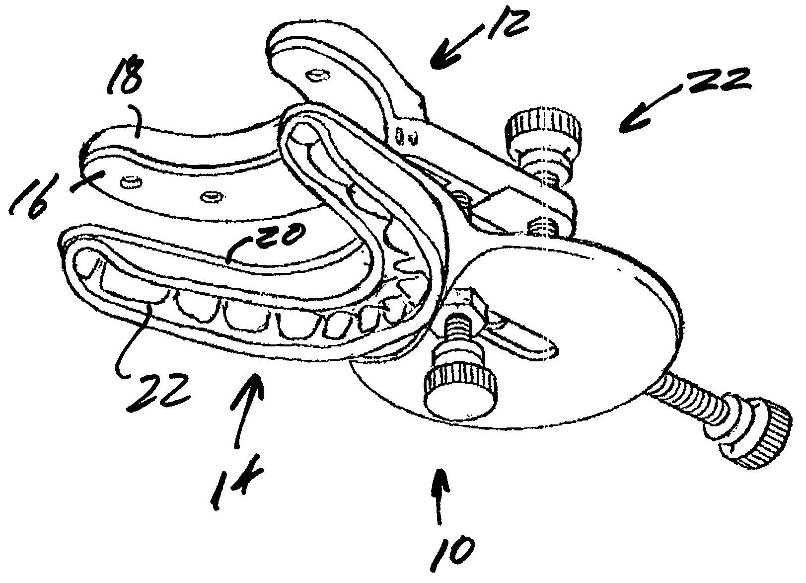
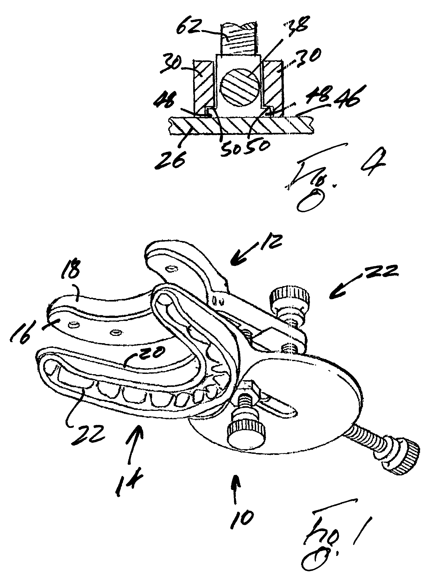
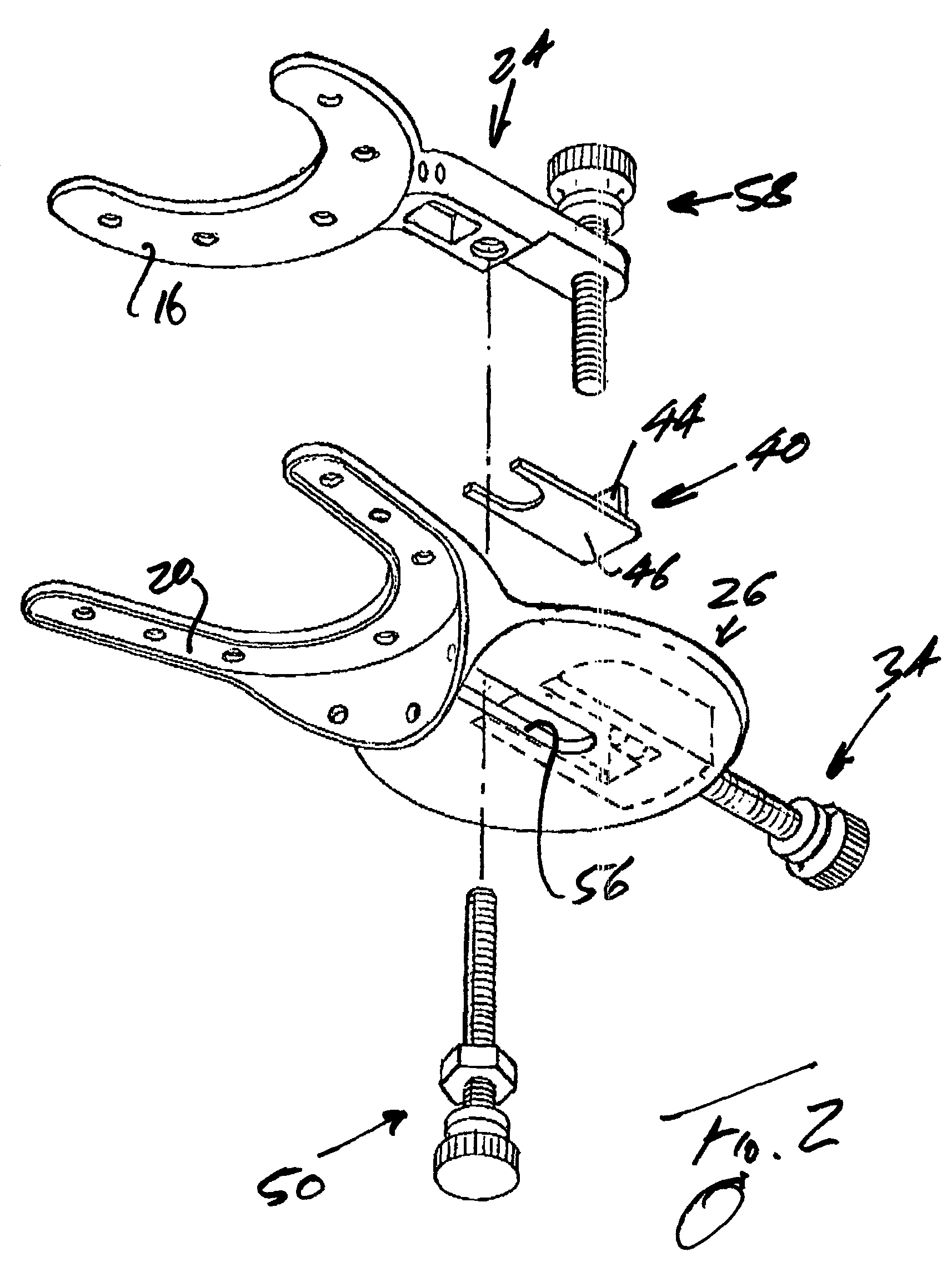
[0023]The mandible positioning device shown in FIG. 1 is indicated generally by reference numeral 10 and comprises a maxillary dentition engagement component or upper bite block indicated generally by reference numeral 12 and a mandibular dentition engagement component or lower bite block indicated generally by reference numeral 14.

[0024]More particularly, the upper bite block 12 comprises a flat U-shaped plate or tray 16 with a dental molding 18, shaped to interfit with the maxillary dentition of a patient, and the lower bite block comprises a U-shaped inverted tray 20 carrying, at its underside, a dental molding 22 shaped for interengagement with the mandibular dentition of the patient.

[0025]The upper and lower bite blocks 12 and 14 are interconnected by a manually adjustable connection indicated generally by reference numeral 22, which projects forwardly from the upper and lower bite blocks 12 and 14 so as to protrude beyond the mouth and lips of a patient (not shown). The manual...


PUM


Abstract

A mandible positioning device or pharyngeal airway adjuster has upper and lower bite blocks and a connection between the upper and lower bite blocks, the connection being manually adjustable for displacing the lower bite block relative to the upper bite block. The adjustable connection protrudes forwardly from the upper and lower bite blocks so that, in use of the device, the manually adjustable member is located and accessible in front of a patient fitted with the mandible positioning device. The manually adjustable connection has screws which are adjustable independently of one another for effecting relative horizontal and vertical displacement, respectively, of the upper and lower bite blocks.

Description

BACKGROUND OF THE INVENTION[0001]1. Field of the Invention[0002]The present invention relates to mandible positioning devices for use as pharyngeal airway adjusters.[0003]2. Description of the Related Art[0004]In patients who are suffering from the sleep disorder known as obstructive sleep apnea, the flesh and muscles of the tongue and throat relax, as the patients attempt to sleep, so that the pharyngeal airway is blocked and, consequently, the patients briefly stop breathing. When this occurs, the patients are awakened by the consequent lack of oxygen and blood, which often occurs with a loud snort or a bodily jerk.[0005]For the proper diagnosis and treatment of patients subject to sleep apnea, polysomnographic testing of the patients is performed in sleep centers or in the patients' homes, while the patients are asleep, to record various factors, including the oxygen level in the patients' blood, the heart action, chest and abdominal movements and brain activity of the patients.[...

Claims


Application Information

Patent Timeline
Patent Type & Authority Patents(United States)
IPC IPC(8): A61F5/56
CPCA61F5/566Y10S602/902
Inventor HALSTROM, LEONARD W.
Owner HALSTROM LEONARD W
Why Eureka
Try Eureka