
Device for displacing an object a certain distance

a technology for displacing objects and distances, applied in mechanical devices, axially engaging brakes, railway braking systems, etc., can solve problems such as drawbacks, and achieve the effect of less space and convenient and reliabl

Inactive Publication Date: 2008-11-11
VOLVO CONSTR EQUIP HLDG SWEDEN AB
View PDF13 Cites 9 Cited by
  • Summary
  • Abstract
  • Description
  • Claims
  • Application Information

AI Technical Summary

Benefits of technology

"The invention provides a device that reduces friction joint problems by using an interconnecting component that forms a friction joint with the driving unit. This interconnecting component is designed to lock against displacement of the object when the object is under load. The interconnecting component and the object are interconnected so that they are locked against displacement relative to each other when the object is acted upon in a direction towards the forward position and when the interconnecting component is acted upon in the opposite direction for driving the object to the rearward position. The interconnecting component and the object are interconnected so that a play occurs between them in a direction which is substantially perpendicular to the intended displacement direction of the object. This play helps to avoid the object transferring an undesired force to the friction joint even if a delimiting surface of the object is displaced in an undesired direction towards the interconnecting component and the friction joint. The interconnecting component and the object are easily and reliably constructed for interconnection by arranging them so that they lock against displacement relative to each other in the current mutual displacement direction when laid in abutment with each other. The possibility to arrange the interconnecting component and the object so that they overlap each other when seen in a direction which is substantially perpendicular to the intended displacement direction of the object is also obtained, which can contribute to a construction that takes up less space."

Problems solved by technology

Although the device described therein works very well in many respects, under certain circumstances it has been shown to have drawbacks.

Method used


Image

  • Device for displacing an object a certain distance
  • Device for displacing an object a certain distance
  • Device for displacing an object a certain distance

Examples


Embodiment Construction

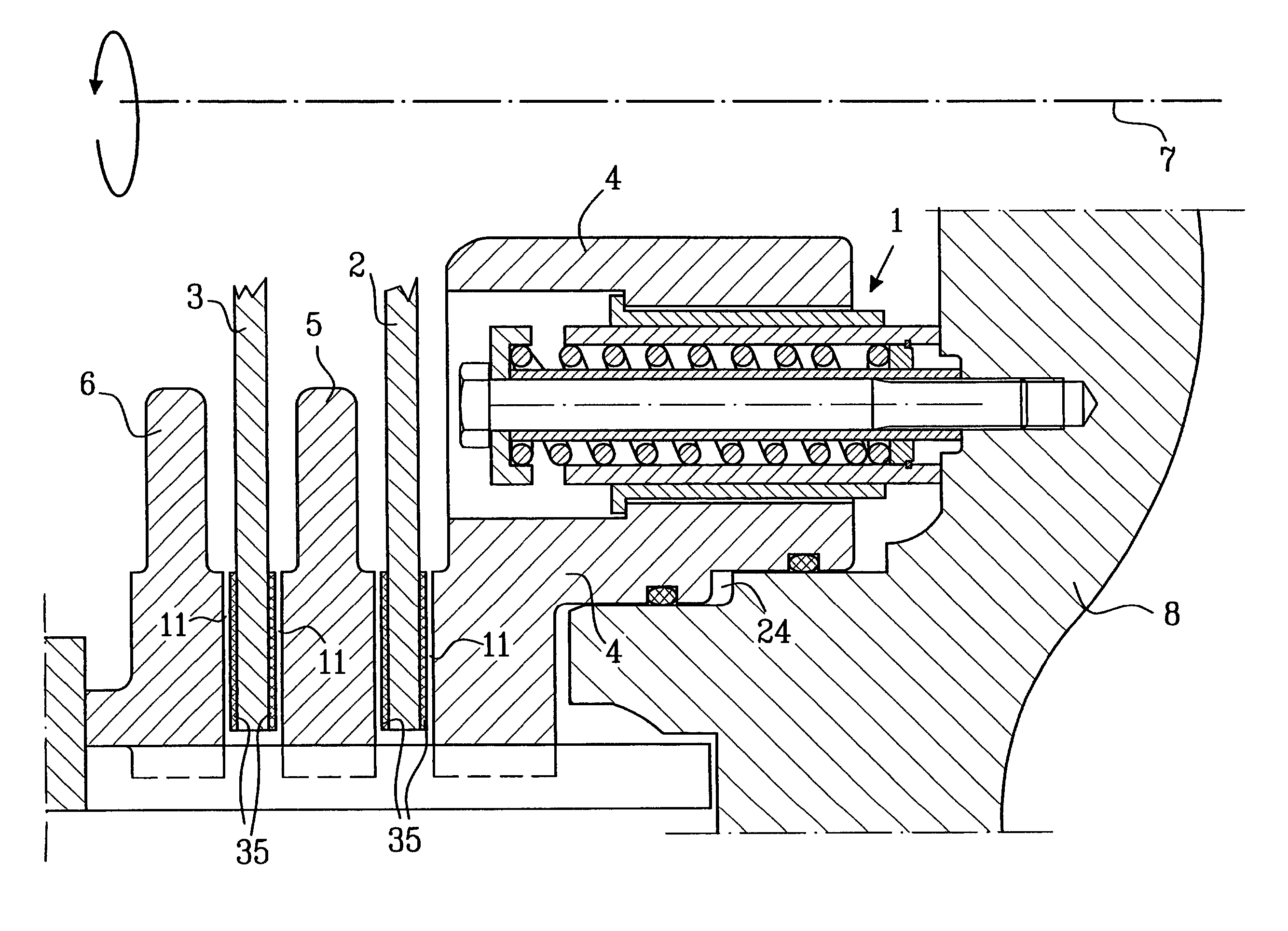
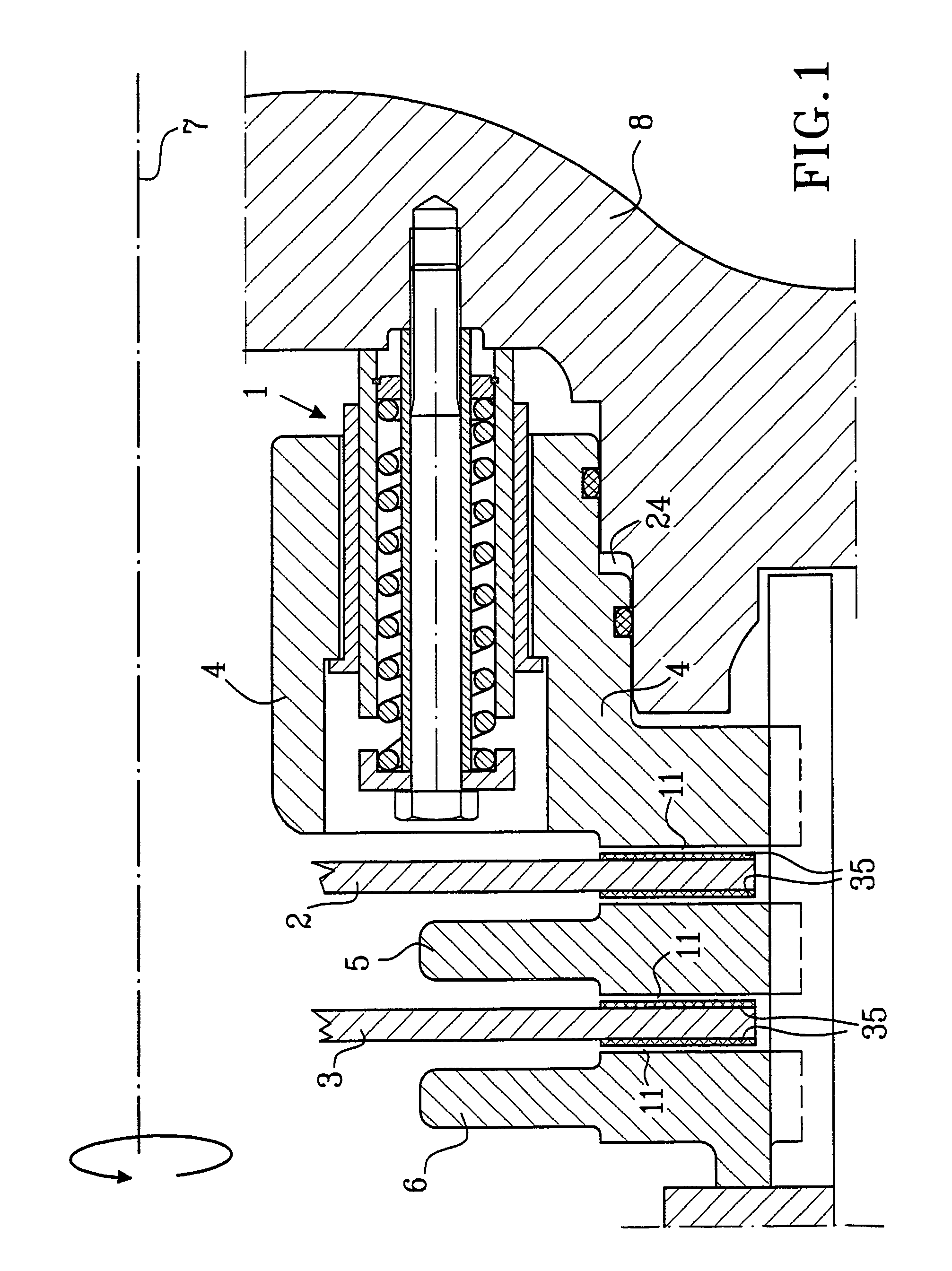
[0016]In FIG. 1, a brake arrangement including a device 1 configured according to the invention is illustrated in a sectional view. The brake arrangement includes two brake discs 2, 3, one 2 of which is arranged to cooperate directly with a piston 4. The brake discs 2, 3 are provided with linings 35 to increase the friction between the discs on one hand, and the piston 4, a stator disc 5 and a counter disc 6 on the other hand. Furthermore, the brake discs 2, 3 are mounted on an axis 7, such as for example a wheel axle of a vehicle. The piston 4 is slidably journalled in a housing 8 for linear displacement between a forward position during braking and a rearward position when play (a spacing distance) 11 occurs between the piston 4 and the brake disc 2 located closest thereto.

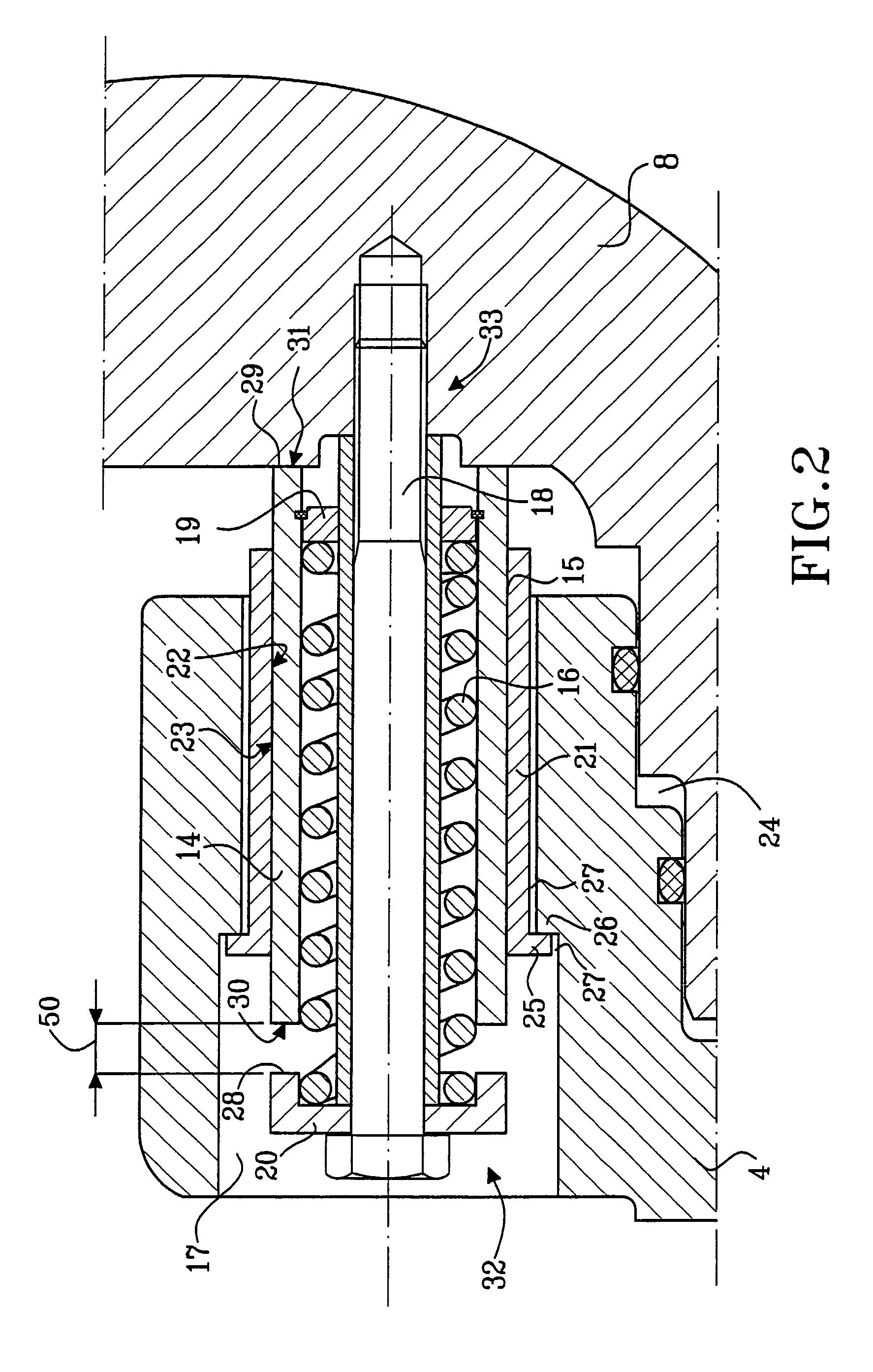
[0017]FIG. 2 shows a device configured according to the invention in an enlarged view, and in FIGS. 3 and 4, it is exemplarily illustrated how the device operates. The device comprises a unit 14 displaceable bet...


PUM


Abstract

A device for displacing an object a certain distance is disclosed. In one particular context, the device may be used in a brake piston. The device features a driving member and an interconnecting member located between the driving member and the object being driven (e.g., the brake piston). The driving member and the interconnecting member form a friction joint between them. The friction joint is strong enough that the driving member can push the object back to a retracted position when it is no longer being actuated, but weak enough that the interconnecting member, and hence the object, can be pushed forward relative to the driving member when the driving member reaches a maximum forward position. This lets the object (e.g., the piston) automatically adjust its non-actuated position so the same amount of fluid is required to move the piston forward as associated brake pads get thinner.

Description

CROSS-REFERENCE TO RELATED APPLICATIONS[0001]The present application is a continuation patent application of International Application No. PCT / SE03 / 00498 filed 25 Mar. 2003 which was published in English pursuant to Article 21(2) of the Patent Cooperation Treaty, and which claims priority to Swedish Application No. 0200966-0 filed 26 Mar. 2002. Said applications are expressly incorporated herein by reference in their entireties.FIELD OF THE INVENTION[0002]The present invention relates to a device for displacing an object a certain distance, and in which the object is displaceable between a forward position and a rearward position. In this regarding, and more specifically, the device comprises (includes, but is not necessarily limited to) a driving unit that is displaceable between a first position and a second position for driving the object a distance corresponding to the distance between the first and the second position. This is accomplished by means of a friction joint that, whe...

Claims


Application Information

Patent Timeline
Patent Type & Authority Patents(United States)
IPC IPC(8): F16D55/40F16D65/54F16D13/75
CPCF16D13/757F16D65/54F16D2055/0058
Inventor KINGSTON, TIMOTHYSTRANDBERG, JONNYANG.KERBLOM, MATS
Owner VOLVO CONSTR EQUIP HLDG SWEDEN AB
Learn More