Rotor collective pitch VS Mu to control flapping and mast/rotor tilt to control rotor RPM

a collective pitch and rotor technology, applied in the field of rotor aircraft, can solve the problems of reducing centrifugal force, difficult to measure flapping during flight, and advancing blades can only provide as much lift moment, and achieve the effect of minimal rotational speed

Active Publication Date: 2008-11-11
JAUNT AIR MOBILITY LLC
View PDF15 Cites 60 Cited by
  • Summary
  • Abstract
  • Description
  • Claims
  • Application Information

AI Technical Summary

Benefits of technology

[0010]In this invention, a controller is utilized for automatic control of the collective pitch at all airspeeds and rotor RPM once the rotor has been significantly unloaded by using a wing for lift and a jet or propeller for forward thrust. The true air speed of the aircraft is measured as well as the rotational speed of the rotor. These speeds are input to the controller, which then determines a Mu of the rotor and varies the collective pitch in relation to the Mu. And once the rotor RPM drops to its minimum RPM, the controller holds this rotor RPM by tilting the rotor mast fore and aft.
[0011]Up to a selected Mu level, such as 0.75, the controller decreases the collective pitch along a predetermined relation or curve as the Mu increases. After the selected level of Mu has been reached and Mu continues to increase, the controller maintains the collective pitch generally constant within a range from about 1.5 and minus 0.5 degrees The controller also varies the tilt of the rotor while above the selected Mu level to maintain a minimum rotational speed. By maintaining the proper rotational speed and controlling the collective pitch, the controller limits flapping within an acceptable degree.

Problems solved by technology

The advancing blade can only provide as much lift moment as the retreating blade.
However, measuring flapping during flight is difficult because the rotor plane of rotation changes in a banked turn and because of rapid changes in air speed or gusts.
As the rotor RPM slows, the centrifugal force decreases until at some point there would not be enough centrifugal force to keep the relatively flexible rotor blades stable.
Also the operator must keep the rotor RPM from going too low whereby there would not be enough centrifugal force to the keep the rotor stable.

Method used


Image

  • Rotor collective pitch VS Mu to control flapping and mast/rotor tilt to control rotor RPM
  • Rotor collective pitch VS Mu to control flapping and mast/rotor tilt to control rotor RPM
  • Rotor collective pitch VS Mu to control flapping and mast/rotor tilt to control rotor RPM

Examples


Embodiment Construction

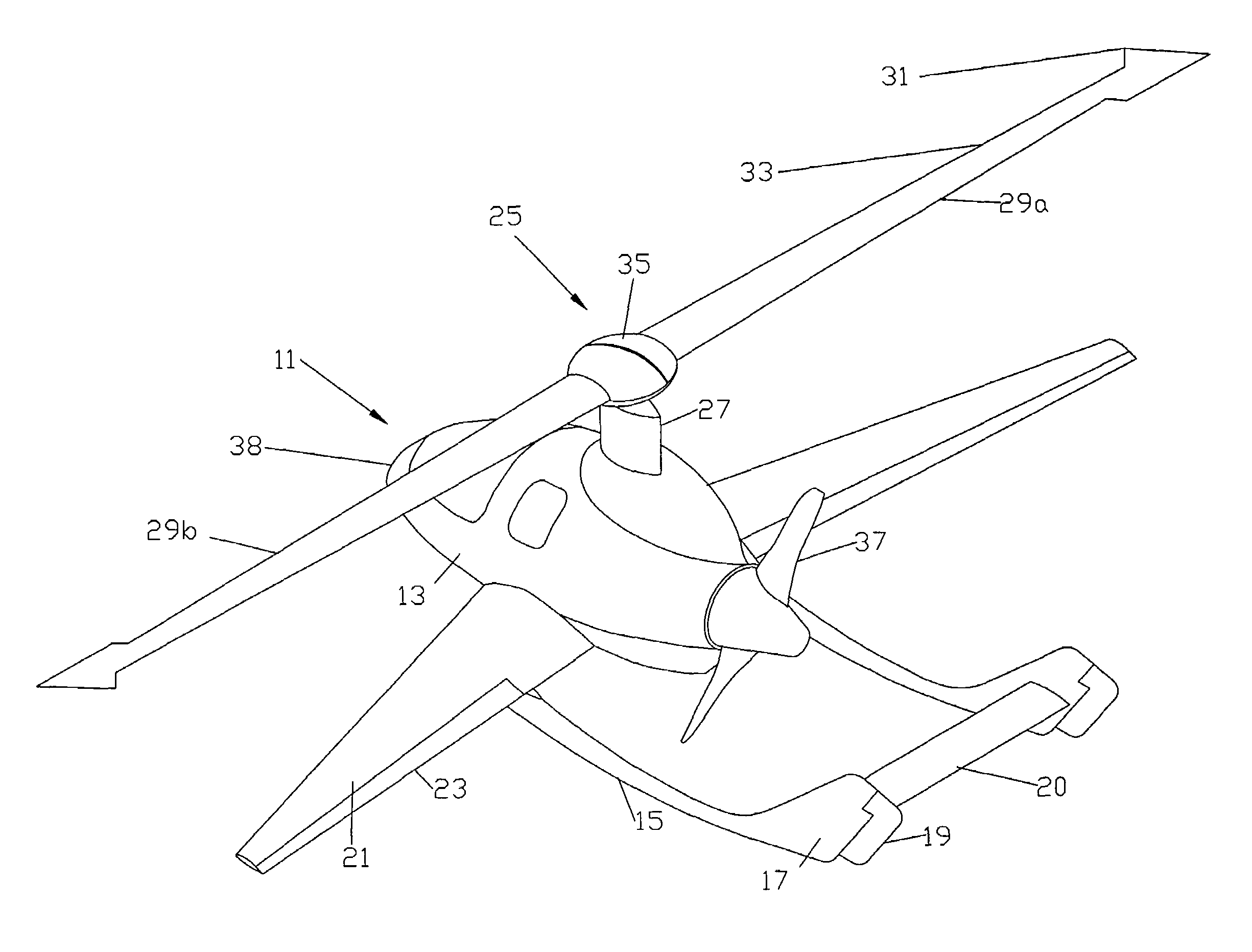
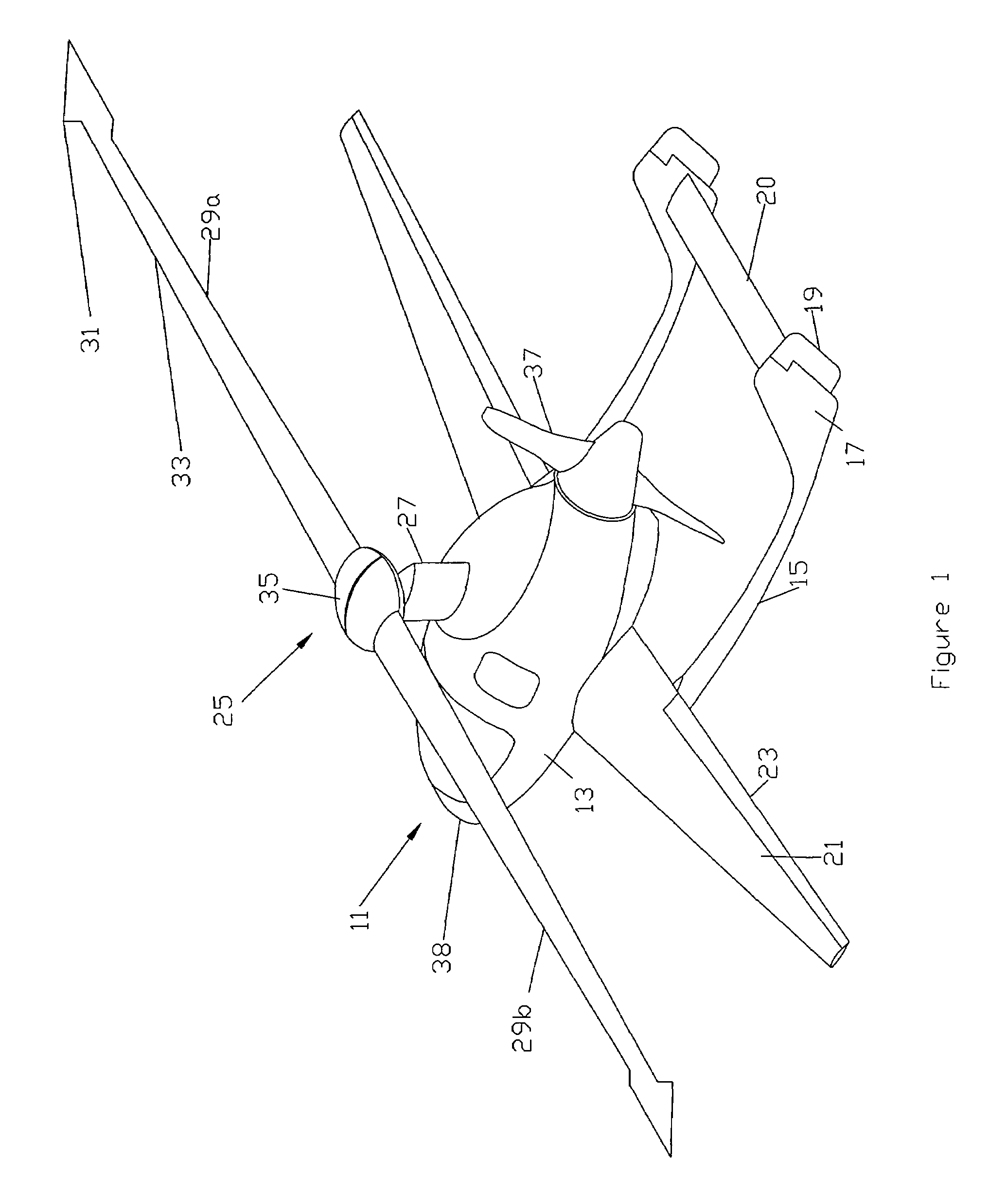
[0020]Referring to FIG. 1, aircraft 11 is a gyroplane having a fuselage 13 with tail booms 15 in this example. A vertical stabilizer 17 is located at the end of each tail boom 15. A rudder 19 is mounted to the aft end of each vertical stabilizer 17. A movable stabilator 20 extends between the aft ends of tail booms 15.

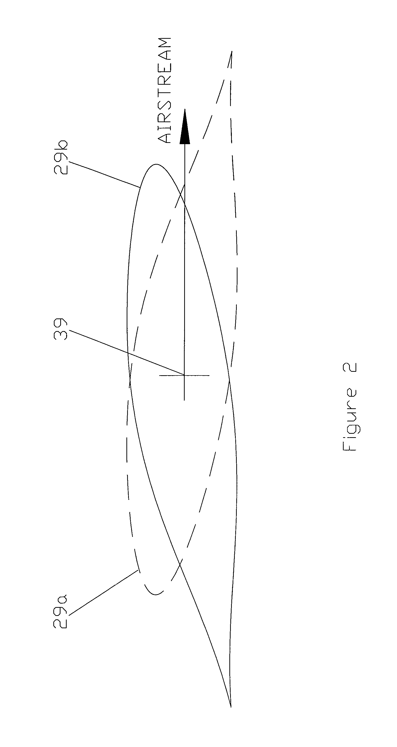
[0021]Fuselage 13 has a pair of wings 21 that provide lift during forward flight. Each wing 21 has an aileron 23 in this embodiment. A rotor 25 is mounted above fuselage 13 on a mast 27. Rotor 25 is shown with two blades 29, but it could have more than two. During each revolution, one blade 29a becomes the advancing blade while the other blade 29b becomes the retreating blade. Blades 29 have tip weights 31 at their tips for providing inertia during take-off and stiffness during slow rotation at cruise speeds. Preferably tip weights 31 are forward of the leading edge 33 of each blade 29. Blades 29 join each other at a hub 35 at the upper end of mast 27. Preferably hub 3...


PUM


Abstract

A method of operating a rotor aircraft involves measuring an airspeed of the aircraft and a rotational speed of the rotor. A controller determines a Mu of the rotor based on the airspeed of the aircraft and the rotational speed of the rotor. The controller varies the collective pitch of the rotor blades in relationship to the Mu, from an inertia powered jump takeoff, through high speed high advance ratio flight, through a low speed landing approach, to a zero or short roll flare landing. In addition as the rotor is unloaded and the rotor slows down, the controller maintains a minimum rotor RPM with the use of a tilting mast.

Description

CROSS-REFERENCE TO RELATED APPLICATION[0001]This application claims priority to provisional application Ser. No. 60 / 628,265, filed Nov. 16, 2004.FIELD OF THE INVENTION[0002]This invention relates in general to rotor aircraft, and in particular to an apparatus for automatically controlling the collective pitch of rotor blades throughout the flight, from an inertia powered jump takeoff, through high speed high advance ratio (Mu greater than about 0.7) flight, through a low speed landing approach, to a zero or short roll flare landing. The invention also relates to controlling the rotor RPM with the use of a tilting mast as the rotor is unloaded and the rotor slows down.BACKGROUND OF THE INVENTION[0003]One type of rotor aircraft has wings, a rotor and a means of forward thrust other than the rotor. The rotor provides most of the lift during short or vertical takeoffs, slow speed flight, and landings, and the wings provide most of the lift during cruise conditions. For a short or zero r...

Claims


Application Information

Patent Timeline
Patent Type & Authority Patents(United States)
IPC IPC(8): B64C27/52
CPCB64C27/02B64C27/021B64C27/024
Inventor CARTER, JR., JAY W.LEWIS, JEFFREY R.
Owner JAUNT AIR MOBILITY LLC
Why Eureka
Try Eureka