Electric vehicle with increased range

a technology of electric vehicles and drive mechanisms, applied in the direction of electric energy vehicles, propulsion by batteries/cells, propulsion using engine-driven generators, etc., can solve problems such as torque generation, and achieve the effects of improving increasing operational safety, and expanding the range of electric vehicles

Inactive Publication Date: 2010-06-17
FEV MOTORENTECHN GMBH
View PDF4 Cites 28 Cited by
  • Summary
  • Abstract
  • Description
  • Claims
  • Application Information

AI Technical Summary

Benefits of technology

[0012]Another configuration provides, for example, that the Wankel engine is used for the startup of the electric vehicle, wherein the Wankel engine generates the electrical energy via the generator, so that the electric vehicle can be driven by means of the electric motors or the electric motor. Such a situation can occur, for example, in case of a disruption or a loss of the storage battery or batteries or when the voltage that is generated by the storage batteries or the storage battery is too small. In addition, there is the possibility that the Wankel engine generates additional electrical energy at the required point in time via the generator. This can be required, for example, during acceleration processes in which not enough energy can be supplied via the storage battery. There is also the possibility that the Wankel engine generates the required voltage by means of the generator when the voltage supply via the storage battery itself is too low for the operation of the electric vehicle. In this way, the range of the electric vehicle can be expanded without having to recharge the storage battery or batteries. In particular, the arrangement of the generator and Wankel engine is therefore suitable for allowing an improvement in the range of the electric vehicle so that it is guaranteed that storage batteries can be recharged by reaching the next recharging station.
[0013]According to one improvement it is provided that a connection between the generator and the Wankel engine and also the generator and the Wankel engine themselves are mounted on a common frame. Advantageously, the frame is arranged on the electric vehicle in this way so that it is replaceable. For example, the frame can be pushed into an opening provided for this purpose, wherein coupling to the other systems of the electric vehicle can be realized, for example, at least partially automatically. Thus, for example, it can be provided that when the frame is installed, pushed in, or inserted, corresponding electrical contacts can be closed that allow the current generated by the generator to be forwarded electrically to the storage battery or batteries or the electric motors. In this way, a bus connection can also be closed, so that a connection for a control device advantageously also housed on the frame to a higher-level control device of the electric vehicle is guaranteed. One or more such electrical contacts can engage, for example, in one or more other electrical counter contacts when the frame is pushed in and thus can establish a connection. In addition, there is the possibility, alternatively and additionally, to be able to establish such a connection between the components involved by means of suitable plug contacts. Another configuration provides that a fuel tank for the Wankel engine is arranged on the frame itself. This allows, for example, for the Wankel engine to be filled up from the outside, before the frame with the Wankel engine and generator is inserted. On the other hand, this also allows installation or disassembly together with the frame, without lines carrying fuel having to be disconnected or reassembled. This increases the operational safety of such a drive module composed of a generator and Wankel engine.
[0014]Another configuration provides that the generator and the Wankel engine are arranged on the common frame so that the housing of the Wankel engine, in alignment viewed laterally, does not project past a housing of the generator. In this way it is possible to generate an extremely compact module that presents a corresponding simplification, particularly with respect to the installation and disassembly. A further improvement results, for example, if there is an exhaust-gas treatment device for the Wankel engine that is fixed to a frame for the generator and Wankel engine. The module formed in this way allows, for example, the entire exhaust-gas line to be examined when the module comprising the generator, Wankel engine, and exhaust-gas treatment device, in addition to the frame, has been removed from the electric motor. Advantageously, an entire exhaust-gas train is arranged on the frame. Another configuration provides that at least one muffler of an exhaust gas train of the Wankel engine is arranged on the frame.
[0015]One preferred configuration provides that, for example, a radiator, a fan, the Wankel engine, the generator, and then a muffler are arranged one after the other on a frame, wherein an exhaust-gas post-treatment device is arranged underneath or on the side of the aforementioned assemblies on the frame. Advantageously, thermal insulation is provided between the exhaust-gas line, in particular, the exhaust-gas post-treatment device and the next components, in particular, the Wankel engine or the generator. One arrangement of the exhaust-gas post-treatment device underneath the frame allows for the frame itself to be arranged in the electric vehicle so that the exhaust-gas post-treatment device then points toward the road surface. This prevents the exhaust-gas post-treatment device and, in particular, also the exhaust-gas line from running somewhat in the interior of the electric vehicle and thus possibly leading to problems with overheating in this area. If it is to be provided to allow the exhaust-gas line to run at least partially in the electric vehicle, corresponding thermal insulation is provided at least for these regions.
[0016]The arrangement of a module having a generator and a Wankel engine, preferably on an installable frame, also allows specific components of a drive mechanism of an electric vehicle to be installed at different positions of the motor vehicle. Thus, according to one configuration it can be provided, for example, that the generator and the Wankel engine are arranged at one end of the vehicle and one or more electric motors are arranged at the opposite end of the vehicle. For example, it can be provided that an electric motor is arranged on each driving wheel of a single driven axle. The generator and also the Wankel engine are arranged in the region of the other axle of the motor vehicle, in this way, for example, a uniform distribution of weight can be achieved across the electric vehicle.
[0017]In addition, there is the possibility of connecting the Wankel engine to a fuel system arranged in the electric vehicle. Thus, for example, the electric vehicle can have a fuel cell that can be operated, in turn, with corresponding fuel, in particular, hydrogen. However, there is also the possibility of operating the fuel cell, for example, with methanol, ethanol, or other hydrocarbons from which the hydrogen is obtained through catalytic processes shortly before use. The use of natural gas for operating the fuel cell is also possible, in which case the Wankel engine would then also advantageously operate with natural gas. In addition, there is the possibility of being able to operate the Wankel engine with diesel fuel, biofuel, and also normal gasoline. The Wankel engine is advantageously sound-encapsulated. Such encapsulation can surround, for example, the frame on which the generator and the Wankel engine are arranged. Fuel provision for the Wankel engine can then be realized advantageously outside of this encapsulation. It is preferred that a fuel tank for the Wankel engine is arranged in its immediate vicinity. In this way it is unnecessary to provide long lines for carrying the fuel in the electric vehicle. In particular, it is preferred to arrange the fuel tank on the frame on winch the Wankel engine is also arranged. In this way a coupling point can be eliminated that otherwise would have to be detached or connected if the frame and the Wankel engine were to be disassembled from the electric vehicle.

Problems solved by technology

The Wankel engine is therefore connected to the generator in a way that allows only the generation of electric energy, but does not generate a torque that would be able to be transferred to the driven wheels of the electric vehicle.

Method used


Image

  • Electric vehicle with increased range
  • Electric vehicle with increased range
  • Electric vehicle with increased range

Examples


Embodiment Construction

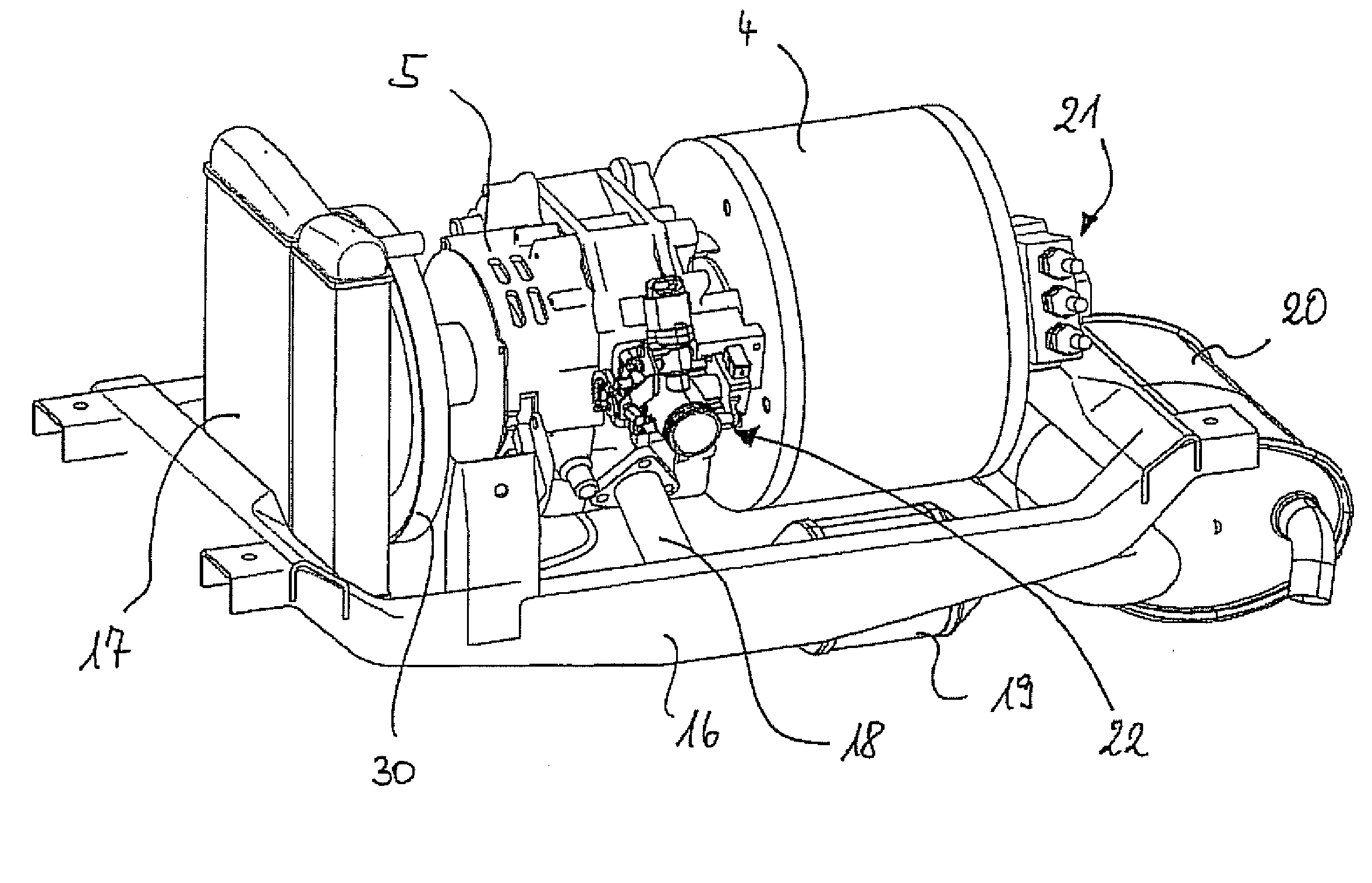
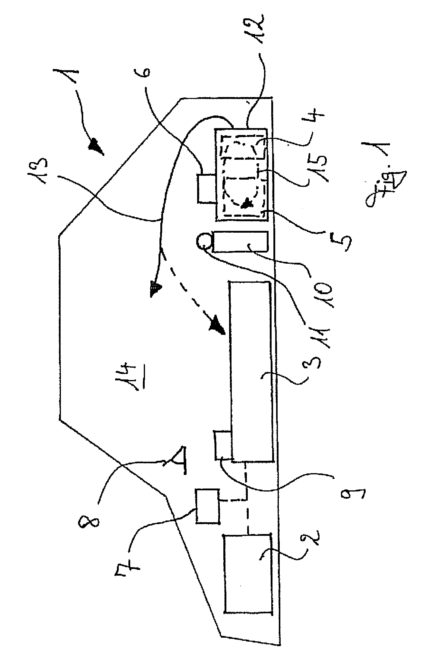
[0030]In an exemplary configuration and schematic view, FIG. 1 shows an electric vehicle 1. The electric vehicle 1 has at least one electric motor 2, at least one storage battery 3, and also a generator 4 and a Wankel engine 5, shown with dashed lines and arranged as a composite component in the electric vehicle 1. With each associated drive axle, the electric motor or motors 2 form the drive train of the electric vehicle 1. In principle, however, the generator 4 with the Wankel engine 5 is a standalone energy generator with which electrical current can be generated for the storage battery 3. The generator 4 and the Wankel engine 5 are advantageously arranged here on a common frame. For example, a control unit 6 can also be provided at or on the frame. The control unit 6 is, for example, a control device that is in contact via a bus system with a higher-level, second control device 7. The higher-level, second control device is capable, in particular, of operating the electric motor ...


PUM


Abstract

The present invention relates to a drive mechanism of an electric vehicle that is realized only by means of one or more electric motors that are connected to at least one storage battery, wherein a generator is provided that can be connected for supplying energy to the drive mechanism, wherein the generator is coupled to a Wankel engine that drives only the generator when needed, but delivers no driving power as torque to the drive train of the electric motor or motors of the drive mechanism. A method for operating an electric vehicle is also presented.

Description

CROSS-REFERENCE TO RELATED APPLICATIONS[0001]This application claims priority of German patent application DE 10 2008 061 295.2 filed Dec. 11, 2008.FIELD OF THE INVENTION[0002]The present invention relates to a drive mechanism of an electric vehicle that is driven only by means of one or more electric motors.BACKGROUND OF THE INVENTION[0003]In various countries, legal regulations require that vehicle fleets must also include electric vehicles, in order to be able to achieve exhaust-gas targets. The advantage of electric vehicles is that no exhaust gases are produced when they are used. Instead, the exhaust gases are generated when the power is generated and thus do not fall within the scope of exhaust-gas emissions of vehicle fleets. In addition, for such energy production, the energy generator is typically operated in an operating range with no load steps, or only very rarely with load steps, and thus the operating range does not change or changes only very rarely. This realizes an...

Claims


Application Information

Patent Timeline
Patent Type & Authority Applications(United States)
IPC IPC(8): B60K6/20B60W10/04B60W20/00B60L50/15
CPCB60K6/24Y02T10/648B60L11/126B60L11/1877B60L2260/28B60L2270/145H02P9/04Y02T10/6217Y02T10/6295Y02T10/646Y02T10/7005Y02T10/705Y02T10/7077B60L2240/34B60K6/46B60L50/62B60L50/66Y02T10/62Y02T10/64Y02T10/70Y02T10/7072
Inventor KALENBORN, MARKUSTIEMANN, CHRISTOFBOLLIG, CHRISTOPH
Owner FEV MOTORENTECHN GMBH
Why Eureka
Try Eureka