
Hybrid vehicle and control method thereof

a hybrid vehicle and control method technology, applied in the direction of engine-driven generator propulsion, external condition input parameters, transportation and packaging, etc., can solve the problems of deterioration of drivability degradation, and battery voltage or residual capacity reduction, so as to improve the system efficiency of hybrid vehicles without deteriorating drivability in reverse travel

Active Publication Date: 2016-11-22
TOYOTA JIDOSHA KK
View PDF15 Cites 0 Cited by
  • Summary
  • Abstract
  • Description
  • Claims
  • Application Information

AI Technical Summary

Benefits of technology

The present invention improves the efficiency of a hybrid vehicle without compromising its performance in reverse travel. This is achieved by setting higher minimum engine rotation speeds based on the steepness of the road and the amount of accelerator pedal depression. The invention also allows for greater electric power output from the battery while maintaining efficiency. Overall, the invention enhances the performance of the hybrid vehicle without negatively impacting its driving experience.

Problems solved by technology

However, in the conventional method disclosed in JP 2004-56922 A, when the battery voltage or the residual capacity of the battery is decreased due to, for example, a low temperature, drivability is deteriorated because the engine rotation speed becomes higher regardless of the driver's intention.
Further, because the engine is maintained at a higher rotation speed for a lower battery voltage or residual capacity of the battery, a problem occurs that the system efficiency of the hybrid vehicle is deteriorated, resulting in a shorter drivable distance.
Therefore, in reverse travel on a steep uphill run, there is a problem that, because the driving force of the second motor generator decreases due to a decrease in the residual capacity of the battery, the drivability is deteriorated due to insufficient acceleration.
A conventional method disclosed in JP 2011-218827 A has a problem that because the drive torque of the second motor generator is increased while driving the engine using the first generator, an energy loss becomes larger and the system efficiency of the hybrid vehicle is deteriorated.

Method used


Image

  • Hybrid vehicle and control method thereof
  • Hybrid vehicle and control method thereof
  • Hybrid vehicle and control method thereof

Examples


Embodiment Construction

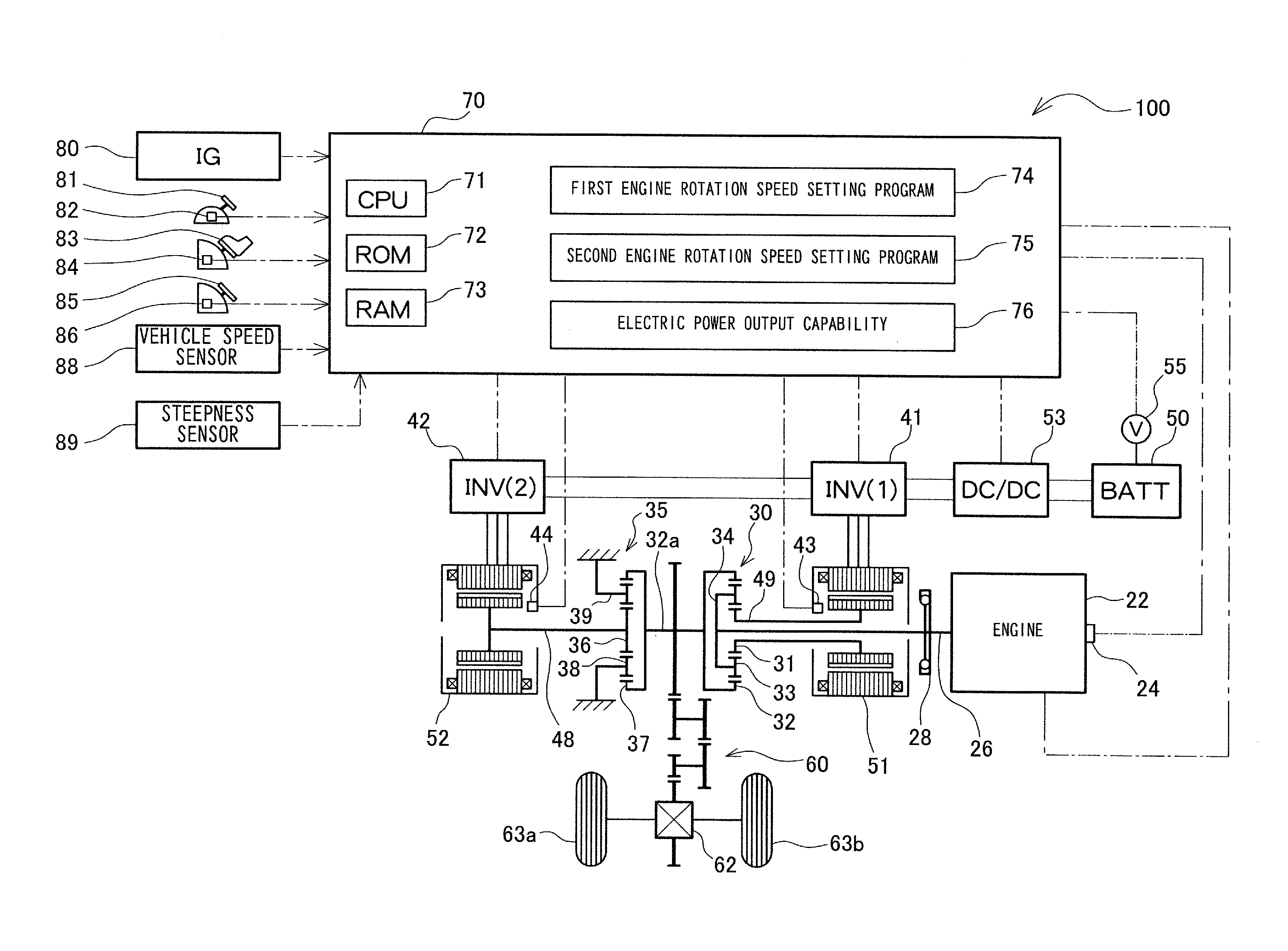
[0026]Embodiments according to the present invention are described below with reference to the attached drawings. As shown in FIG. 1, a hybrid vehicle according to an embodiment of the present invention is provided with an engine 22, a three-shaft type planetary gear mechanism 30 serving as a motive power distribution mechanism connected to a craft shaft 26 (output shaft of the engine 22) via a damper 28, a first motor generator (MG1) 51 connected to the planetary gear mechanism 30, a deceleration gear 35 mounted on a ring gear shaft 32a (vehicle drive shaft) connected to the planetary gear mechanism 30, a second motor generator (MG2) 52 connected to the deceleration gear 35, a battery 50 which is a chargeable and dischargeable secondary battery, and a controller 70.

[0027]The planetary gear mechanism 30 includes an external sun gear 31, an internal ring gear 32 positioned concentric to the sun gear 31, two or more pinion gears 33 which mesh with the sun gear 31 and the ring gear 32,...


PUM


Abstract

A hybrid vehicle provided with an engine, a first motor generator, a planetary gear mechanism, a second motor generator, a battery, a battery state sensing unit which senses the voltage and the residual capacity of the battery, a steepness sensor which senses the uphill steepness, an accelerator pedal depression amount sensor, and a controller. The minimum rotation speed of the engine is set in accordance with the uphill steepness and the accelerator pedal depression amount, when the hybrid vehicle is travelling in reverse and the battery is charged with the voltage of the battery equal to or below a first threshold or the residual capacity of the battery equal to or below a second threshold.

Description

PRIORITY INFORMATION[0001]This application claims priority to Japanese Patent Application No. 2014-032330, filed on Feb. 21, 2014, which is incorporated herein by reference in its entirety.BACKGROUND[0002]Technical Field[0003]The present invention relates to a configuration of a hybrid vehicle and a control method thereof.[0004]Related Art[0005]Recently, hybrid vehicles combining an engine and a motor generator are widely used. Such a hybrid vehicle often uses a vehicle drive system including a planetary gear mechanism which distributes motive power transmitted from an engine to a first motor generator and a vehicle drive shaft; and a second motor generator which transmits motive power to the vehicle drive shaft. Because the planetary gear mechanism cannot rotate the vehicle drive shaft in the reverse direction which is opposite to the rotation direction of the engine, a hybrid vehicle having such a vehicle drive system performs reverse travel by rotating the second motor generator ...

Claims


Application Information

Patent Timeline
Patent Type & Authority Patents(United States)
IPC IPC(8): B60K6/445B60W10/08B60W10/06B60K6/365B60W30/18B60L50/16
CPCB60K6/445B60K6/365B60W10/06B60W10/08B60W20/13B60W30/18B60W30/18036B60W2540/10B60W2550/142B60W2710/0644B60W2710/244Y02T10/6239Y02T10/6286Y10S903/93B60W10/26B60W2552/15Y02T10/62
Inventor TAKAHASHI, YOSHIMITSU
Owner TOYOTA JIDOSHA KK
Learn More