Light up bouncing and entertainment apparatuses

a technology of entertainment apparatus and pogo stick, which is applied in the field of pogo stick, can solve the problems of operator's feet occasionally falling off the foot pads, the lights of the footpad are serious defects, and the observer and operator of the pogo stick are unable to see clearly, so as to increase the pleasure and enjoyment, and advance the popularity of the pogo stick

Active Publication Date: 2008-11-11
FLYBAR
View PDF31 Cites 8 Cited by
  • Summary
  • Abstract
  • Description
  • Claims
  • Application Information

AI Technical Summary

Benefits of technology

[0011]With the desire to advance the popularity of the pogo stick, various patterns of lights may be placed on the housing of a pogo stick. The patterns of lights may illuminate as the user of the pogo stick jumps up and down on the pogo stick. This increases the pleasure and enjoyment while promoting the entertainment uses for both the user / operator of the pogo stick and the observer / audience of the pogo stick.

Problems solved by technology

This presented problems for both the observer and operator of the pogo stick.
Additionally, footpad lights present a serious defect since they might become damaged due to their location near the operator's feet.
It is common that while using a pogo stick the feet of the operator may occasionally slip off the foot pads and hit the lights located near or on the foot pads.
Thus, it is not desirable to place lights on the footpads.
Further, lights placed near or on the location of the footpads can present a danger to the operator.
When feet slip off the footpads during use and cause damage to footpad lights, a loose electrical connection or even an open circuit may result.
These present dangerous conditions that could lead to electrical shock and other problems for the operator.
However, lights in this position are dangerous because the user of the pogo stick looks down instead of looking up at the field of view, making it all too easy to land in an awkward or hazardous position.
Also, such lights are not intended for viewing by observers, who may have a hard time viewing such lights, as the operator's hands may be in the way.

Method used


Image

  • Light up bouncing and entertainment apparatuses
  • Light up bouncing and entertainment apparatuses
  • Light up bouncing and entertainment apparatuses

Examples


Embodiment Construction

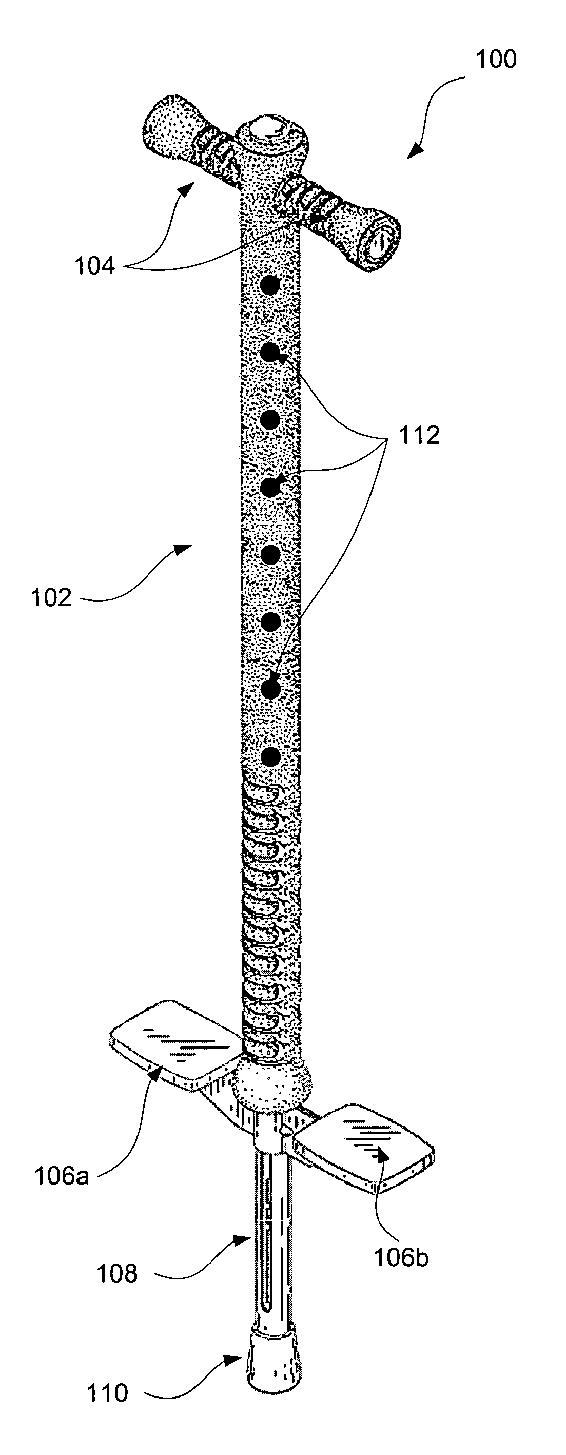
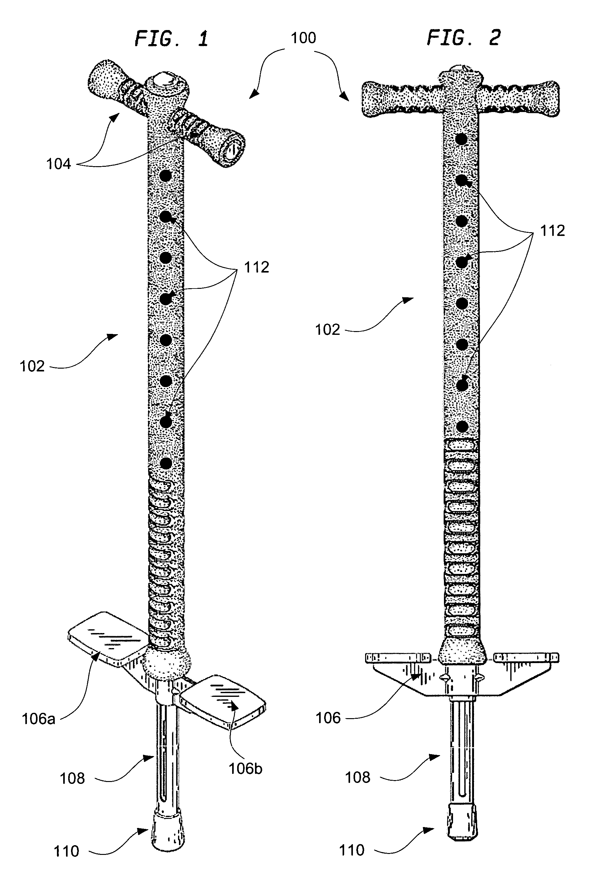
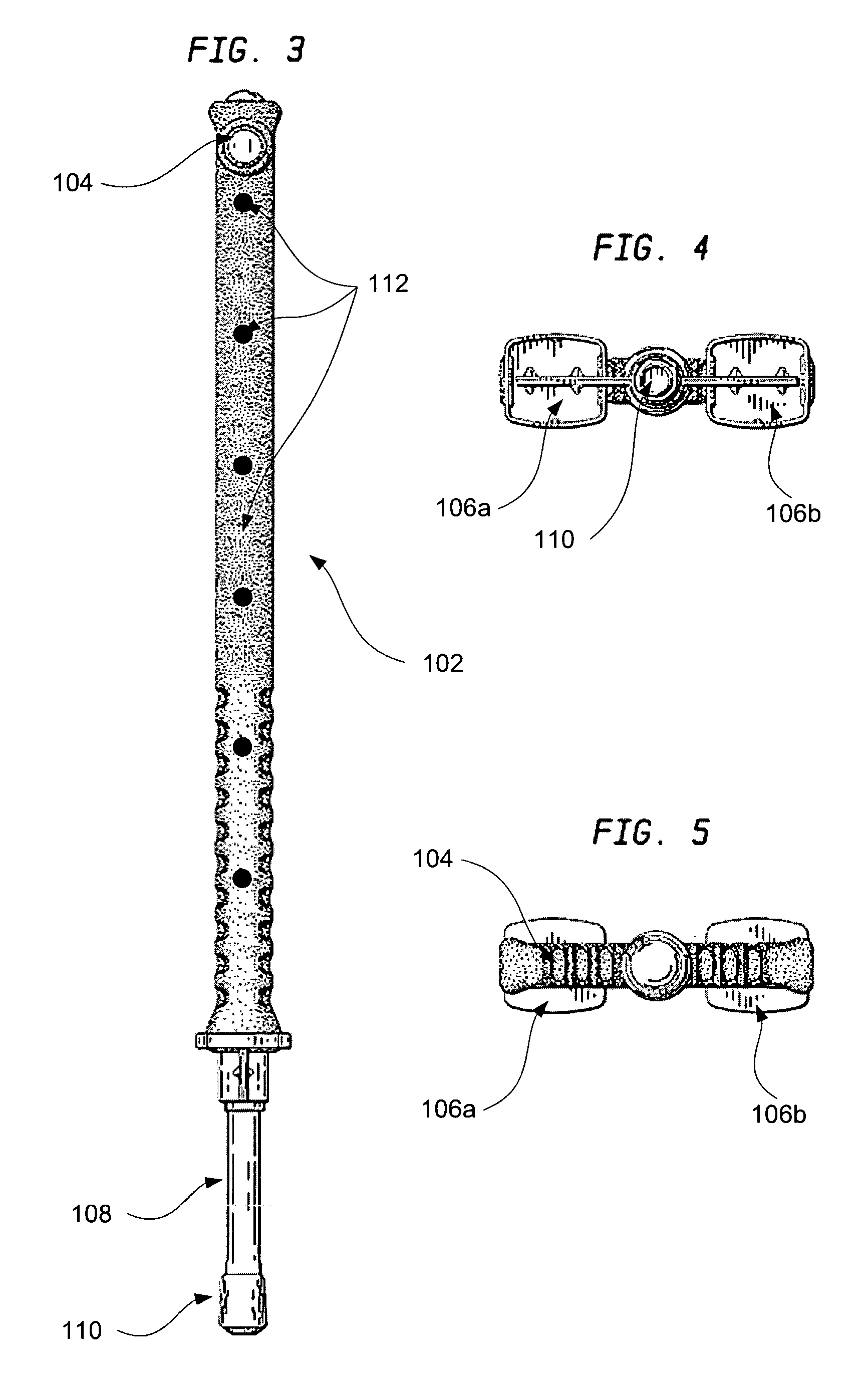
[0053]Referring to FIGS. 1-5, a preferred embodiment of the present invention is shown as pogo stick 100. The pogo stick 100 includes a housing unit 102. The pogo stick 100 preferably also includes handle bars 104, a foot support plate 106, a piston 108, and a piston endcap 110 attached to the housing 102. A plurality of lights 112 are preferably disposed on the housing unit 102. In this embodiment, the pogo stick 100 is also referred to herein as a single support housing pogo stick.

[0054]The housing unit 102 has a top and bottom and can be an elongated cylinder as shown, or alternatively can be an elongated rectangular rod or other configuration. Contained within the housing unit 102 is a spring type mechanism (not shown) capable of allowing the piston 108 to move up and down relative to the housing unit 102 and the foot support plate 106, which is preferably rigidly attached to the housing unit 102. The piston 108 and the spring type mechanism may be conventional configurations fo...


PUM


Abstract

The present invention relates to a pogo stick structure, more particularly, a pogo stick comprising a housing unit, foot support plate, piston, spring mechanism, and handlebars. The external portion of the housing unit includes a plurality of LED lights that light in accordance with the piston impinging the ground. LED lights displayed on the housing may be of different colors and may be arranged in a multitude of ways. Furthermore, the displayed LED lights may light in different patterns and at different times as a result of an electronic processing unit. A foam layer may cover the housing and protect the lights from accidental damage. The foam layer and lights may also be used with other entertainment devices such as stick horses.

Description

CROSS-REFERENCE TO RELATED APPLICATION[0001]This application is a continuation-in-part of U.S. patent application Ser. No. 11 / 207,523, filed Aug. 19, 2005, entitled Light Up Bouncing Apparatus, the entire disclosure of which is hereby expressly incorporated by reference herein.BACKGROUND OF THE INVENTION[0002]This invention relates generally to pogo sticks and, more particularly, to pogo sticks having flashing lights which illuminate in response to bouncing on the pogo stick.[0003]A pogo stick can be generally described as a bouncing apparatus. A user of a pogo stick steps on a foot rest extending from a housing unit, holds handles attached to the housing and hops repeatedly. The user bounces up and down as a piston is forced upward on a spring-like mechanism.[0004]Pogo sticks first became popular in the 1920's. Since then, pogo sticks have been used both for leisure and entertainment purposes. For example, the New York hippodrome chorus girls performed entire shows on them, marriag...

Claims


Application Information

Patent Timeline
Patent Type & Authority Patents(United States)
IPC IPC(8): A63B25/08A63B21/008
CPCA63B25/08A63B21/0087A63B21/05A63B71/0622A63B2207/02A63B2208/12A63B2225/20A63B2225/50A63B2225/74
Inventor ARGINSKY, IRWINSAMORE, DOUGLASJARGOWSKY, MYRNA
Owner FLYBAR
Why Eureka
Try Eureka