Web welding system

a welding system and web technology, applied in the field of welding systems, can solve the problems of affecting the welding quality of webs, so as to reduce the quality of welding, reduce the welding accuracy, and improve the welding quality

Active Publication Date: 2008-11-11
ZUIKO CORP
View PDF13 Cites 66 Cited by
  • Summary
  • Abstract
  • Description
  • Claims
  • Application Information

AI Technical Summary

Benefits of technology

[0004]However, in such a conventional welding system, since a plurality of ultrasonic horns are provided around one anvil roller, the anvil roller is subject to large loads caused by ultrasonic vibration energy. Thus, the durability of the anvil roller may be impaired. Further, when the ultrasonic horns apply ultrasonic vibration simultaneously to the webs to weld the webs, the vibration causes positional displacement of the anvil roller. Accordingly, positional accuracy of welding may be decreased or quality of welding may be decreased.
[0005]An object of the present invention is to provide a new welding system wherein the positional accuracy of welding and the quality of welding are improved and the durability of the anvil roller is enhanced.

Problems solved by technology

However, in such a conventional welding system, since a plurality of ultrasonic horns are provided around one anvil roller, the anvil roller is subject to large loads caused by ultrasonic vibration energy.
Thus, the durability of the anvil roller may be impaired.
Further, when the ultrasonic horns apply ultrasonic vibration simultaneously to the webs to weld the webs, the vibration causes positional displacement of the anvil roller.

Method used


Image

  • Web welding system
  • Web welding system
  • Web welding system

Examples


first embodiment

[0059]In the following description, an important part of a web welding system of the present invention will first be described in the first embodiment, and a velocity-changing device that is provided in the web welding system will then be described.

[0060]FIGS. 1 to 3 show the first embodiment.

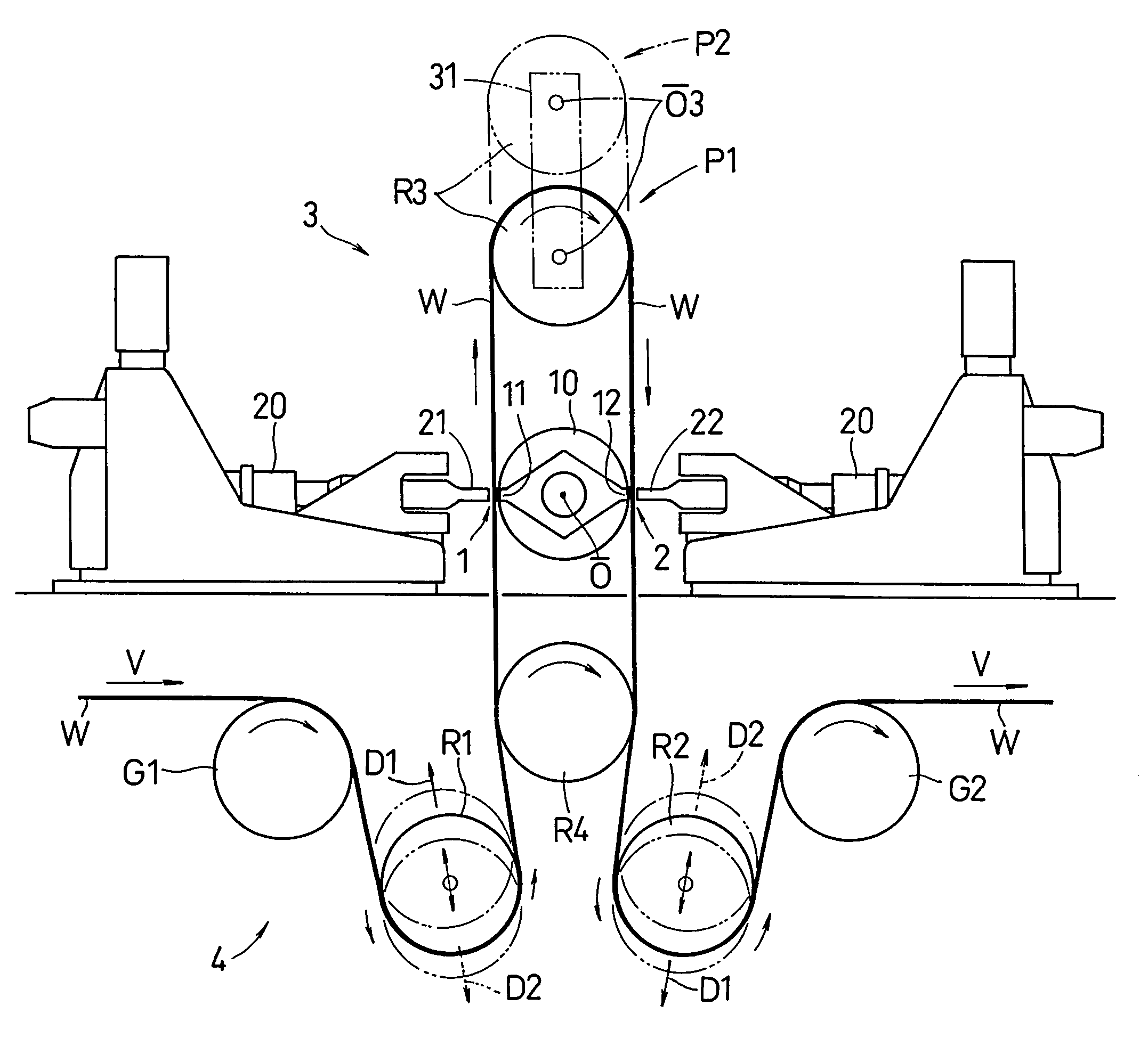
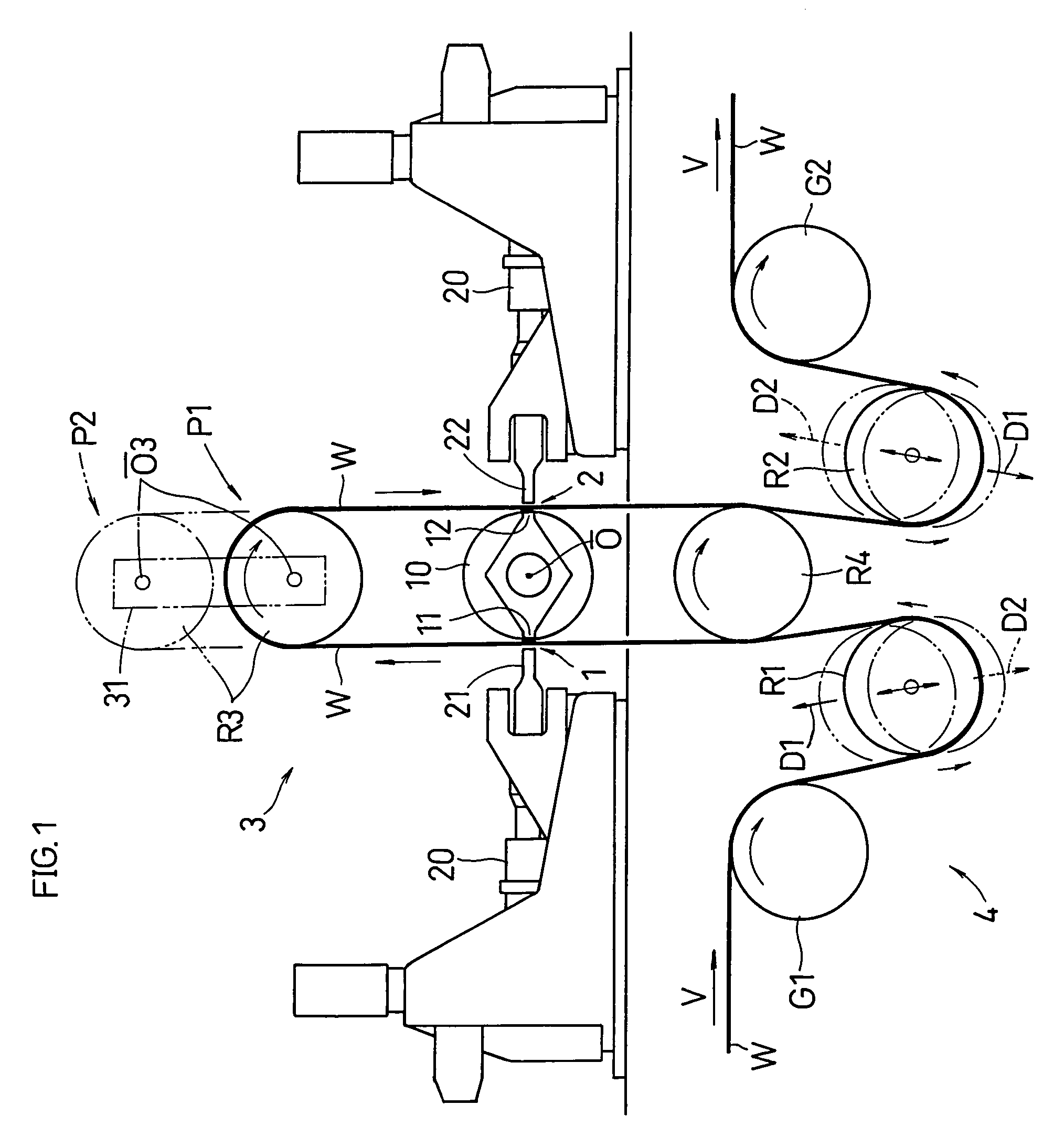
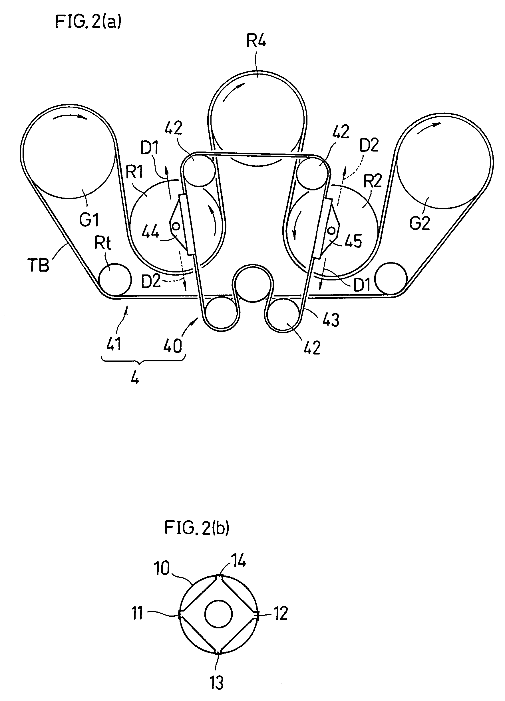
[0061]The present system includes an ultrasonic welding device (ultrasonic welder) for welding together a plurality of webs W, which are stacked on each other, while carrying the webs W. The ultrasonic welder includes: an anvil roller 10 including a pair of anvils 11, 12; a first ultrasonic horn 21 and a second ultrasonic horn 22 that apply vibration energy to the webs W in cooperation with the pair of anvils 11, 12; a pair of ultrasonic devices 20, 20 that generates ultrasonic vibration in the ultrasonic horns 21, 22, respectively.

[0062]High frequency mechanical vibrations is transmitted to the ultrasonic horns 21, 22 so that the webs W passing between the ultrasonic horn 21, 22 and the anvil ...

second embodiment

[0108]FIG. 5 shows the

[0109]As shown in FIG. 5, the first drive roller R4 which is in contact with the webs W need not necessarily be provided.

third embodiment

[0110]FIG. 6 shows the

[0111]As shown in FIG. 6, guides (guide members) T1, T2, T3 for guiding the flow of the webs W may be provided around the three rollers R1, R2, R3, respectively. Similarly, guides T8, T9 for guiding the flow of the webs W may be provided around the first and second guide roller G1, G2. In addition, guides T4, T5 for guiding the flow of the webs W flowing into the first drive roller R4 and guides T6, T7 for guiding the flow of the webs W flowing out of the first drive roller R4 may be provided. These guides T1 to T9 are useful for carrying the webs W smoothly, especially in a case where the weight of the webs W is unbalanced, for example, the webs W is composed of a stack of a plurality of webs including absorbent bodies.

[0112]While preferred embodiments of the present invention have been described above with reference to the drawings, obvious variations and modifications will readily occur to those skilled in the art upon reading the present specification.

[0113...


PUM

PropertyMeasurementUnit
vibration energyaaaaaaaaaa
timeaaaaaaaaaa
moving velocityaaaaaaaaaa

Abstract

An object of the present invention is to provide a welding system wherein the positional accuracy of welding and the quality of welding are improved. The present welding system includes an ultrasonic welder for welding a plurality of webs W together while carrying the webs W. The ultrasonic welder includes: an anvil roller 10 including a pair of anvils 11, 12; a first ultrasonic horn 21 and a second ultrasonic horn 22 that apply vibration energy to the webs W in cooperation with the pair of anvils 11, 12. The pair of anvils 11, 12 are provided symmetrically with each other with respect to an axis line O of the anvils roller 10. The first and second ultrasonic horns 21, 22 apply the vibration energy to the webs W simultaneously while each of the anvils 11, 12 faces the first or second ultrasonic horn 21, 22.

Description

TECHNICAL FIELD[0001]The present invention relates to a welding system for welding a plurality of webs, which is sometimes referred to as “sealing”.BACKGROUND ART[0002]Hitherto, a welding system wherein a plurality of ultrasonic horns are provided around one anvil roller is known (for example, the following first patent document).[0003]The first patent document: Japanese Laid-Open Patent Publication No. 2004-330622 (abstract)DISCLOSURE OF THE INVENTION[0004]However, in such a conventional welding system, since a plurality of ultrasonic horns are provided around one anvil roller, the anvil roller is subject to large loads caused by ultrasonic vibration energy. Thus, the durability of the anvil roller may be impaired. Further, when the ultrasonic horns apply ultrasonic vibration simultaneously to the webs to weld the webs, the vibration causes positional displacement of the anvil roller. Accordingly, positional accuracy of welding may be decreased or quality of welding may be decrease...

Claims


Application Information

Patent Timeline
Patent Type & Authority Patents(United States)
IPC IPC(8): B32B37/00B29C65/08B65H23/188
CPCA61F13/15739A61F13/15772B29C66/83511B65H23/1882B29C66/8412B29C66/81465B29C66/93441B29C66/93451B29C65/086B29L2031/4878B65H2513/104B29C66/3452B29C66/92445B29C66/431B29C66/1122B29C66/73921B29C66/433B29C65/088B29C66/843B65H2513/10B29C66/91645
Inventor NAKAKADO, MASAKI
Owner ZUIKO CORP
Why Eureka
Try Eureka