Drive for an internal combustion engine comprising an oil wet toothed belt and a tensioning shoe

a technology of internal combustion engine and tensioning shoe, which is applied in the direction of driving belt, analogue computer, analog and hybrid computing, etc., can solve the problems of increasing power dissipation, reducing active working life, and deteriorating the belt, so as to reduce power dissipation and achieve the effect of satisfying durability requirements and reducing power dissipation

Active Publication Date: 2012-12-04
DAYCO EURO
View PDF41 Cites 0 Cited by
  • Summary
  • Abstract
  • Description
  • Claims
  • Application Information

AI Technical Summary

Benefits of technology

[0008]It is the object of the present invention to make an engine oil wet belt drive, comprising a shoe having an optimised geometry for reducing the power dissipated by friction of the belt on the shoe, without impairing the durability requirements required in automotive applications.

Problems solved by technology

However, a shoe having a non-optimised longitudinal profile causes an increase of power dissipated by friction against the belt and the subsequent temperature increase deteriorates the belt and reduces the active working life thereof.

Method used


Image

  • Drive for an internal combustion engine comprising an oil wet toothed belt and a tensioning shoe
  • Drive for an internal combustion engine comprising an oil wet toothed belt and a tensioning shoe
  • Drive for an internal combustion engine comprising an oil wet toothed belt and a tensioning shoe

Examples


first embodiment

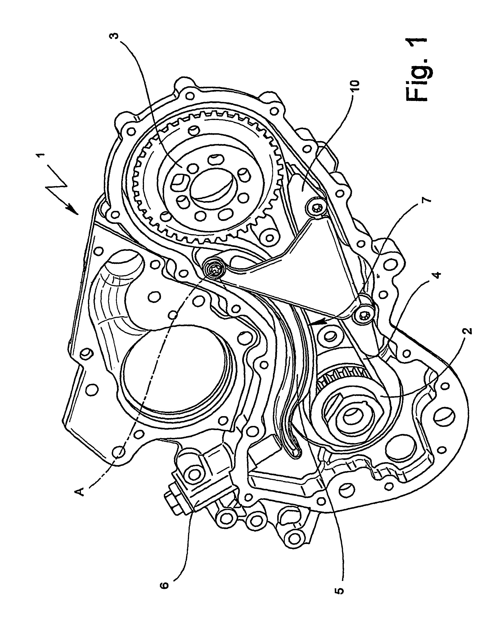
[0091] the reference drive was adapted to a belt drive by means of a shoe obtained according to the method of the present invention (FIG. 1) and without modifying any other geometric data, including the position of axis A.

[0092]

TABLE 1LAYOUTCoordinatesN. ofPitchTransmission[mm]Winding angleMeshingDescriptionteethdiameters [mm]ratioXY[Deg][mm]teethDrive2060.641.000.000.00199.22105.4211.00Gliding—−1202.90483.00−414.518.77−92.01—shoe—−402.90261.53−81.475.22−18.35—Driven40121.280.50179.28172.01236.15249.9326.00Shoe—−252.90−10.17156.1810.65−23.50——−202.9013.84149.2550.73−89.83—

[0093]FIG. 3 relates to a curve obtained by points by means of the use of the above-described method and applied to the drive having the geometry specified in table 1.

[0094]Specifically, FIG. 3 is obtained with a belt of length equal to 809.76 mm. Furthermore, the negative sign of the diameters in table 1 is a convention to indicate that the corresponding arcs of circumference cooperate with the back of toothing be...

second embodiment

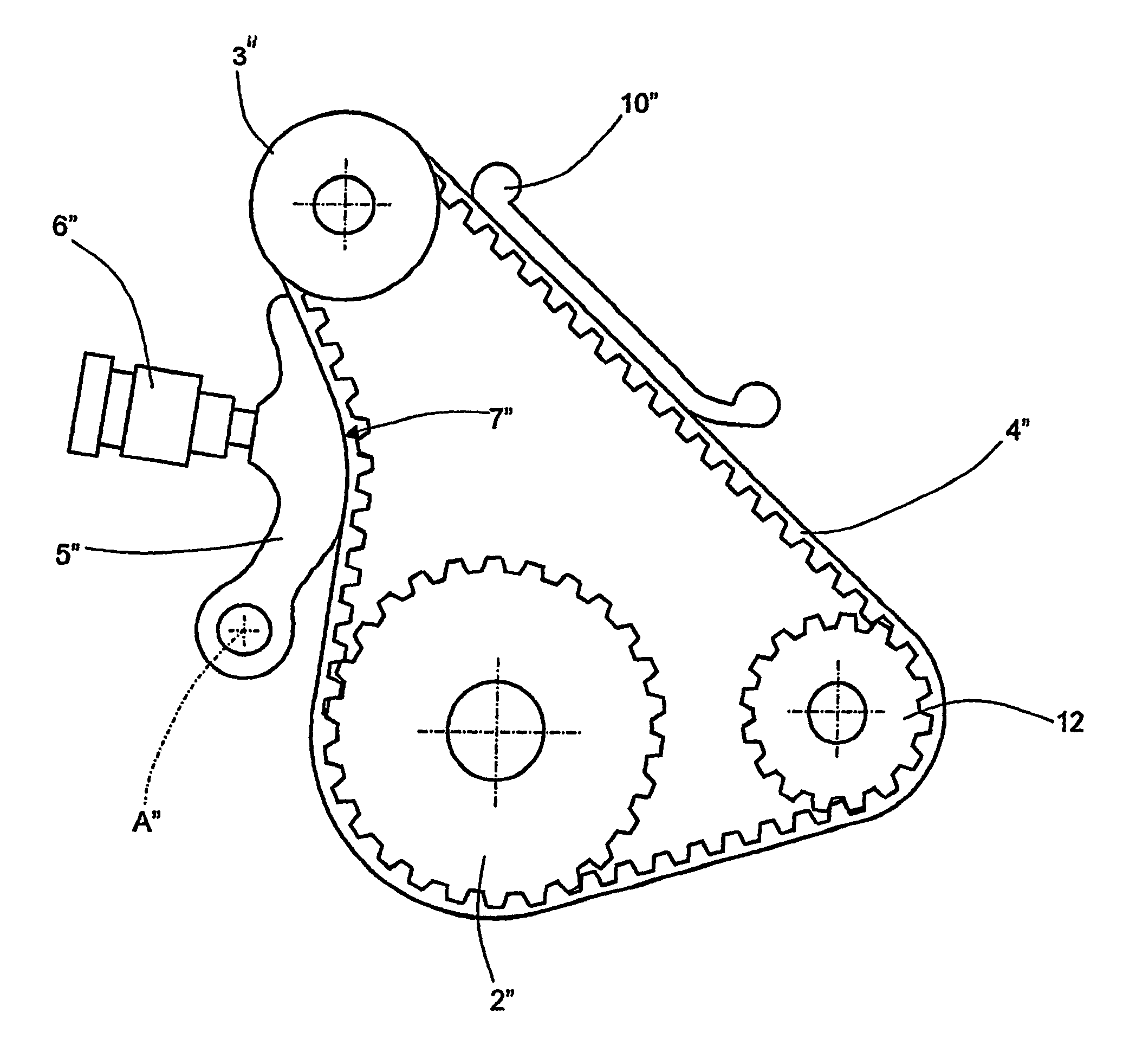
[0112]In a second embodiment, shown in FIG. 4, the geometry of the drive is defined by the “wheel diagram” in table 4. Specifically, the elements in FIG. 4 functionally identical or similar to those of drive 1 are followed by “″”. The drive in FIG. 4 connects drive pulley 2″ to a pair of driven pulleys 3″, 12 to control corresponding balancing countershafts. Specifically, the balancing countershaft connected to pulley 3″ with 24 teeth is further connected to a gear so that the total transmission ratio is equal to 2.

[0113]

TABLE 4Coordinates N. ofPitchTransmission[mm]Winding angleMeshingDescriptionteethdiameters [mm]ratioXY[Deg][mm]teethDrive42100.271.000.000.00123.74108.2714.00Countershaf2457.301.7584.1435.12130.0365.02 8.00Gliding—−277.4455.07214.4630.09−72.84—Countershaf2150.132.00−81.00118.00184.1680.5610.00Tensioner—−73.04−88.7244.4547.84−30.49—

[0114]Furthermore, the length of toothed belt 4 is equal to 637.3 mm and the coordinates of axis A are x=−69.0 mm, y=−1.5 mm. Furthermore...


PUM


Abstract

A drive for an internal combustion engine having a predetermined take-up rate (TU) and comprising a drive pulley, a driven pulley, a shoe and an oil wet toothed belt cooperating in contact with a guiding surface of the shoe, presenting an optimized winding angle (α) of the guiding surface to decrease the power dissipated on the toothed belt.

Description

TECHNICAL FIELD[0001]The present invention relates to a drive for an internal combustion engine comprising an oil wet toothed belt and one or more tensioning shoes.BACKGROUND ART[0002]There have recently been developed engines for motor vehicles comprising a timing belt having an oil wet belt and capable of meeting at least the same durability requirements as dry belt drives or chain drives. It is specified that the expression “oil wet” used in the description and in the claims refers both to applications in which the belt is at least partially immersed in oil at rest and to applications in which the oil is conveyed on the belt, e.g. by spraying by means of a specific nozzle or by splashing due to the action of the belt or the pulleys.[0003]Specifically, the environment in which the belt drive of the present invention works may be the same as that in which a chain drive works.[0004]With respect to chain drives, belt drives present lower costs and much lower loss due to friction. Fur...

Claims


Application Information

Patent Timeline
Patent Type & Authority Patents(United States)
IPC IPC(8): G06F17/00F16H7/08
CPCF16H7/18F16H2007/0872F16G1/28
Inventor ROLANDO, ADRIANO
Owner DAYCO EURO
Why Eureka
Try Eureka