Endoscope image processing apparatus

a technology of image processing and endoscope, which is applied in the field of endoscope image processing system, can solve the problems of time-consuming work, difficult to display an image using an appropriate domain within the number of pixels, and too much time for diagnosis

Active Publication Date: 2008-11-11
OLYMPUS CORP
View PDF24 Cites 60 Cited by
  • Summary
  • Abstract
  • Description
  • Claims
  • Application Information

AI Technical Summary

Problems solved by technology

However, in this type of image processing system, if a different type of electronic endoscope is employed and, for example, a solid-state image pickup device incorporated in the endoscope offers a different number of pixels, it is hard to display an image using an appropriate domain within the number of pixels.
In other words, time-consuming work is needed in order to designate a domain, which is used for display, according to the number of pixels offered by the solid-state image pickup device incorporated in the electronic endoscope to be employed actually.
Consequently, it takes too much time for diagnosis.

Method used


Image

  • Endoscope image processing apparatus
  • Endoscope image processing apparatus
  • Endoscope image processing apparatus

Examples


first embodiment

[0034]To begin with, the present invention will be described.

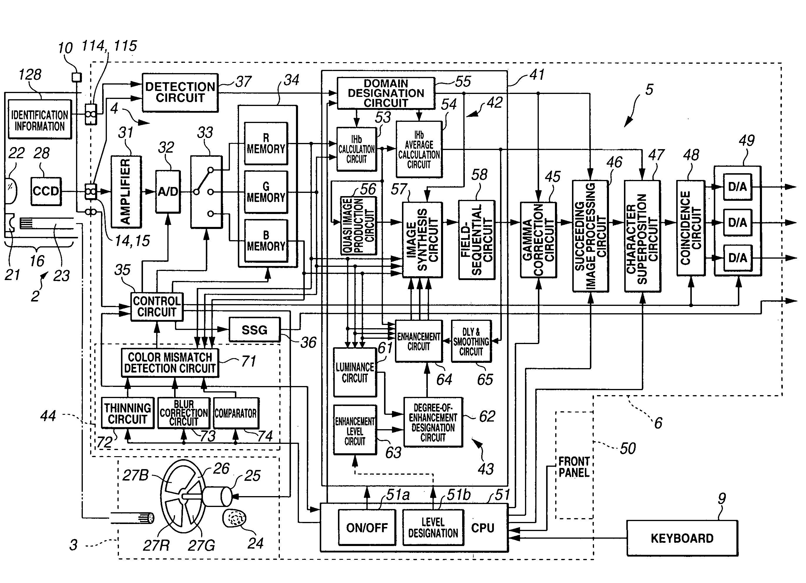
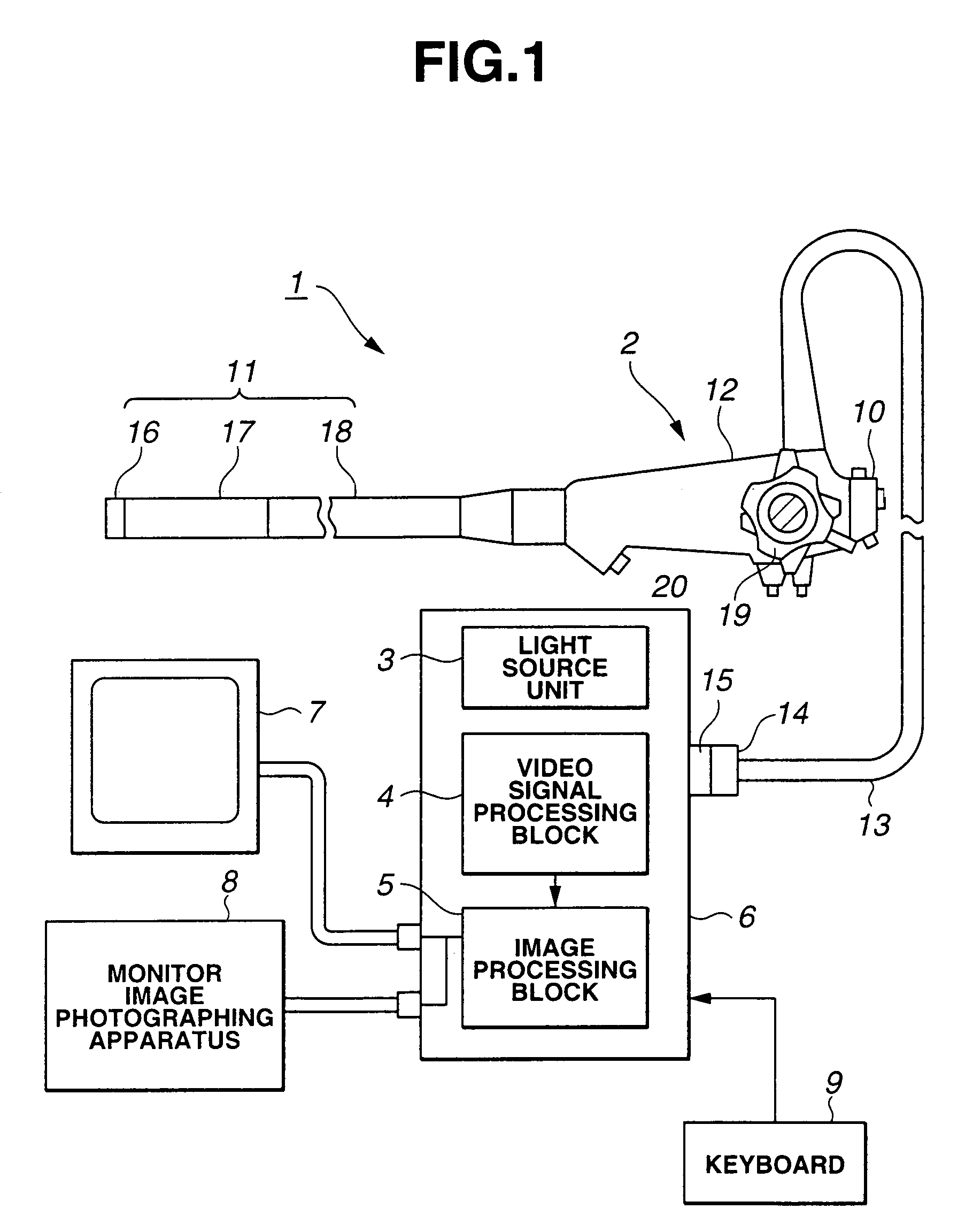
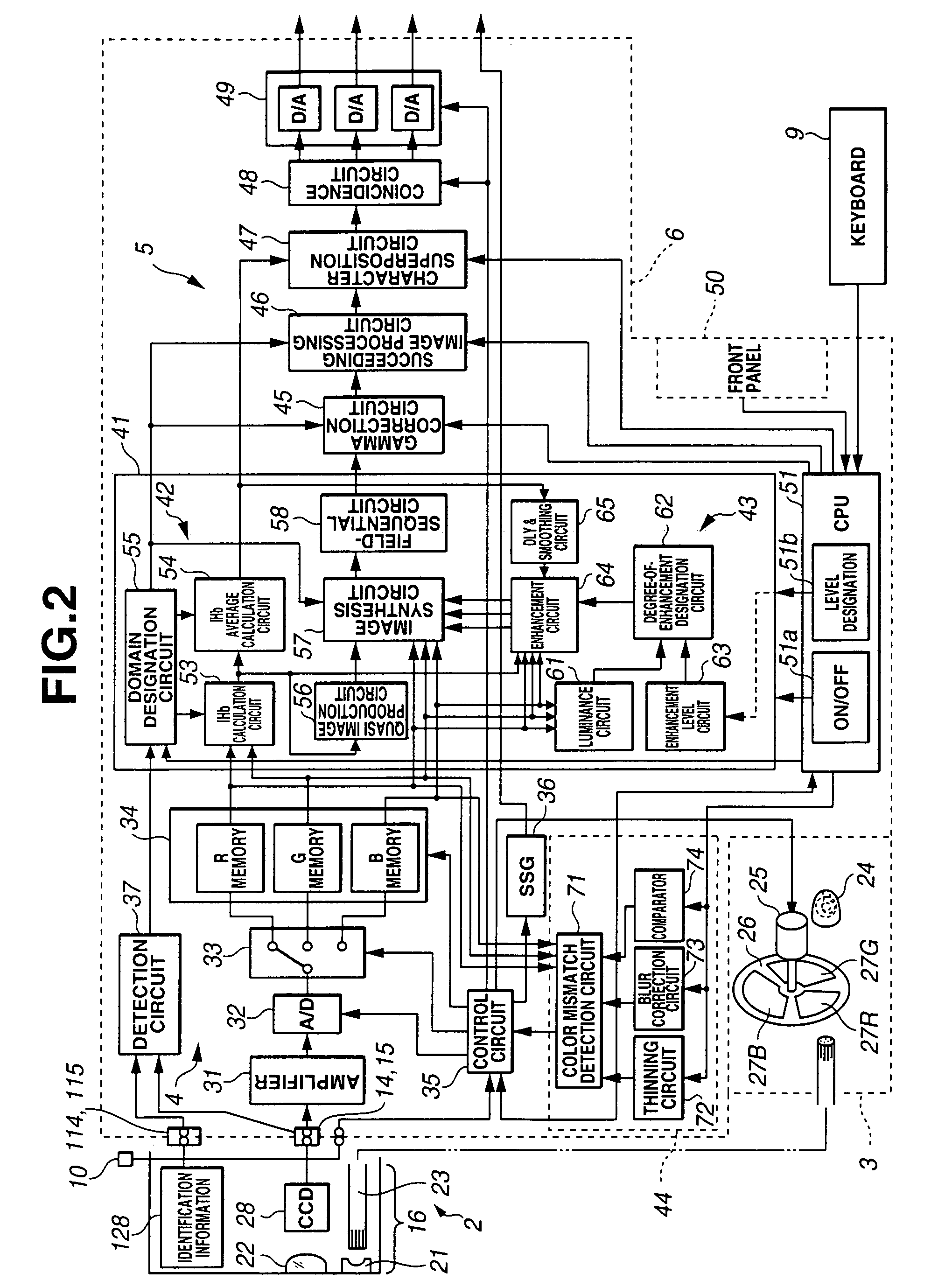
[0035]FIG. 1 shows the overall configuration of an endoscope system including the first embodiment. FIG. 2 shows the internal configuration of the endoscope system. FIG. 3 shows the configuration of an image processing block. FIG. 4 shows the configuration of an IHb processing circuit. Herein, an IHb value is a value correlating to an amount of hemoglobin that is regarded as hematic information.

[0036]FIG. 5A, FIG. 5B, and FIG. 5C show examples of a normal image and a major quasi image displayed on a monitor. FIG. 6 describes actions to be performed for detecting a type of CCD and producing a mask signal associated with the type of CCD. FIG. 7 describes typical actions to be performed for displaying a quasi color image. FIG. 8 shows an example of a freeze designation menu screen image. FIG. 9 shows an example of an IHb designation menu screen image. FIG. 10 describes actions to be performed for displaying a quasi color imag...

second embodiment

[0163]As long as the second embodiment is concerned, when a quasi color image is displayed according to the process described in FIG. 14, gamma correction is disabled. When a raw image is displayed, gamma correction is enabled. According to the process described in FIG. 15, gamma correction is enabled or disabled according to the setting of enabling or disabling (on or off) of gamma correction.

[0164]Moreover, according to the present embodiment, once color enhancement is enabled, a degree of color enhancement can be varied depending on a luminance level according to whether a designated enhancement level is equal to or higher than a certain level, or lower than it.

[0165]FIG. 16 indicates the above mechanism. FIG. 16 presents the effectiveness in color enhancement in accordance with the present embodiment, and also presents the effectiveness therein in accordance with a related art for comparison.

[0166]As seen from FIG. 16, according to the related art, when luminance is high, even i...


PUM


Abstract

An endoscopic image processing system processes an image signal produced by picking up the image of an intracavitary region of an object to be examined using an electronic endoscope. The endoscopic image processing system includes a detection unit that detects at least one of the type of electronic endoscope connected to the endoscopic image processing system, based on information inherent to the electronic endoscope, and the type of image pickup device incorporated in the connected electronic endoscope, and an image processing unit processes the image signal produced by the electronic endoscope according to the signal level of the image signal. A domain designation unit designates a first domain to be processed by the image processing unit within the image data according to the detected type of electronic endoscope.

Description

CROSS-REFERENCE TO RELATED APPLICATION[0001]The present application claims a priority from Japanese Patent Application No. 2002-70498 filed in Japan on Mar. 14, 2002, and Japanese Patent Application No. 2003-65561 filed in Japan on Mar. 11, 2003. The contents of the disclosures are cited in the description, claims, and drawings of the present applicant.[0002]This application is the U.S. national phase of a 371 of PCT / JP03 / 03071,filed Mar. 14, 2003.TECHNICAL FIELD[0003]The present invention relates to an endoscopic image processing system that processes an image signal produced by an endoscope.BACKGROUND ART[0004]In recent years, endoscopes have been widely adopted in the field of medicine or the like. Aside from endoscopes that perform normal image processing, there are endoscopes that perform image processing to calculate hematic information concerning a region to be examined in an object to be examined.[0005]For example, Japanese Unexamined Patent Application Publication No. 2001-...

Claims


Application Information

Patent Timeline
Patent Type & Authority Patents(United States)
IPC IPC(8): A61B1/04H04N7/18A61B1/00A61B1/05A61B5/00G06T1/00
CPCA61B1/00059A61B1/05A61B1/0638A61B5/1455A61B1/00009A61B1/0005A61B1/043A61B1/000095A61B1/00
Inventor KANEKO, KAZUMA
Owner OLYMPUS CORP
Why Eureka
Try Eureka