Hinge

a technology of hinge and wing, applied in the field of hinge, to prevent oil leakag

Inactive Publication Date: 2008-11-18
SHIN ZU SHING
View PDF6 Cites 28 Cited by
  • Summary
  • Abstract
  • Description
  • Claims
  • Application Information

AI Technical Summary

Benefits of technology

[0007]The primary objective of the present invention is to provide a hinge that is sturdy and so configured that oil leakage is prevented.

Problems solved by technology

However, the conventional hinge does not have any stop element in the opening of the stationary bracket so that the lubricating oil would leak out and cover with dust to influence the hinge to pivot.

Method used


Image

  • Hinge
  • Hinge
  • Hinge

Examples


Embodiment Construction

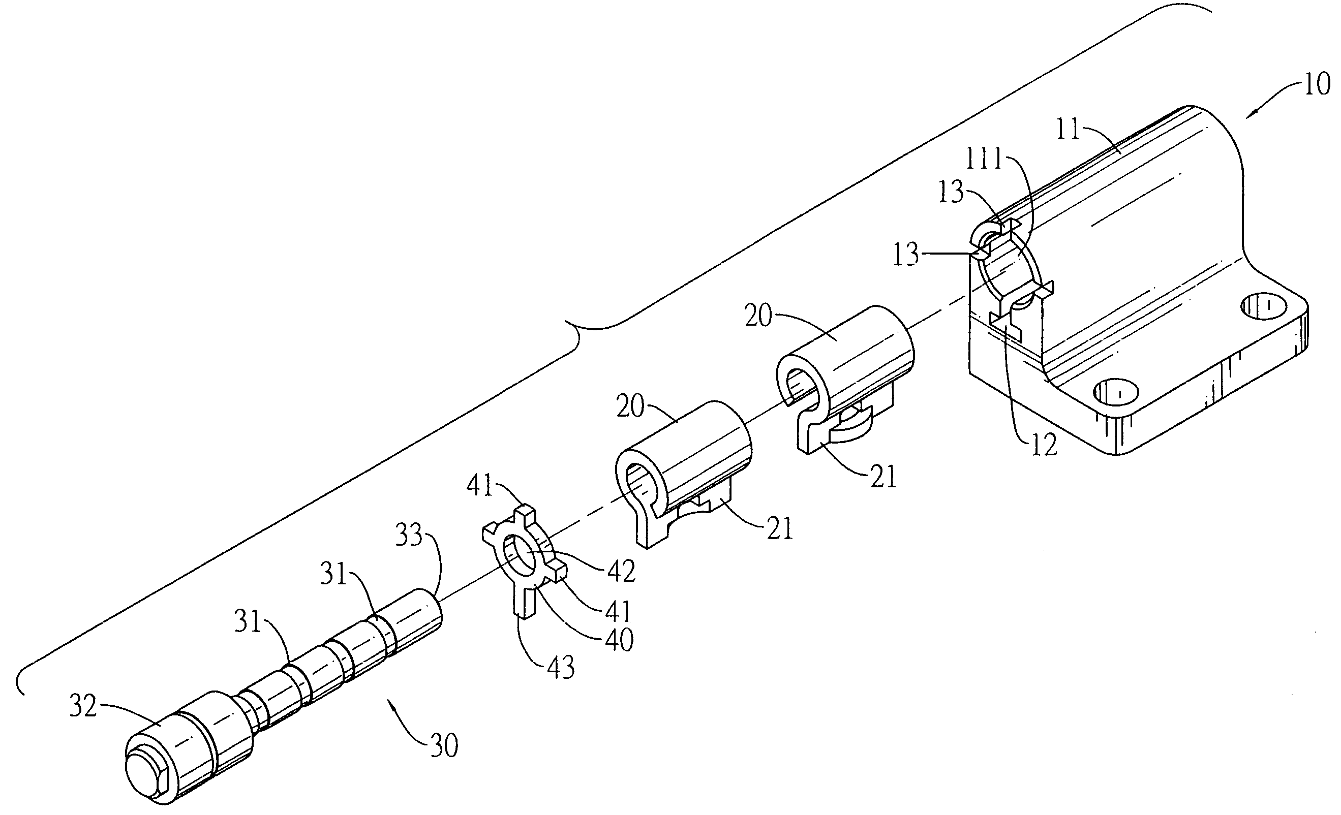
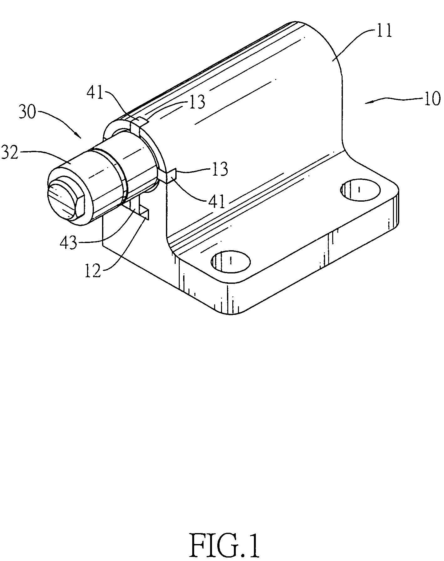
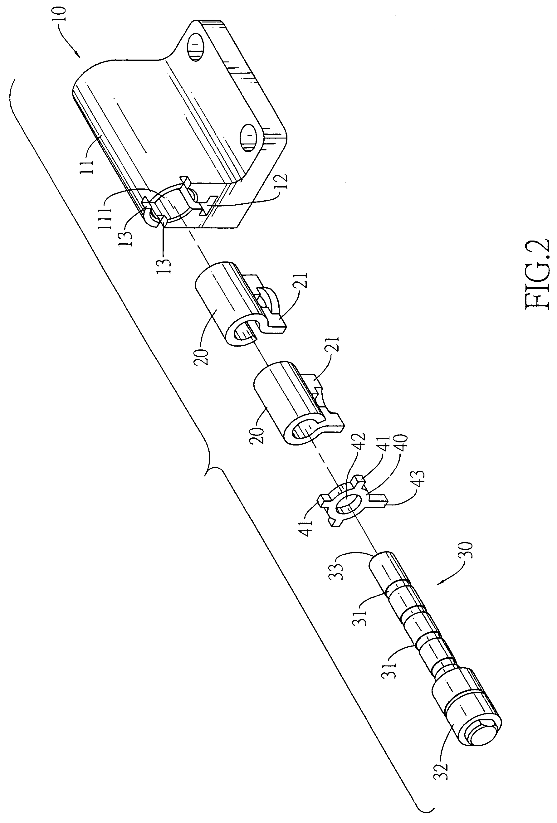
[0017]With reference to FIGS. 1 to 3, a hinge in accordance with the present invention, which is mounted in an appliance with a base and a cover, has a stationary bracket (10), a pintle (30), two resilient spacer (20) and a stop element (40).

[0018]The stationary bracket (10) is attached to the base of the appliance and has a sleeve (11), multiple limiting notches (13) and an optional elongated keyway (12). The sleeve (11) is tubular and has a first end, a second end, a first opening (111) and an optional second opening (112). The first opening (111) is formed in the first end of the sleeve (11). The second opening (112) is formed in the second end of the sleeve (11) and has an inner diameter. The limiting notches (13) are formed in the first end of the sleeve (11) and are adjacent to the first opening (111). The elongated keyway (12) is formed longitudinally in the stationary bracket (10) and communicates with the first opening ( 111) in the sleeve (11).

[0019]Each resilient spacer (...


PUM


Abstract

A hinge has a stationary bracket having multiple limiting slots, two resilient spacers, a pintle having a bar and an enlarged head, a stop element mounted in the pintle between the enlarged head and the resilient spacers and having multiple limiting tabs corresponding to and mounted in the limiting slots in the stationary bracket to make the limiting tab and the pintle to seal the opening and a keyhole provided the pintle to mount in and having an inner diameter being not bigger than an outer diameter of the bar to provide a tightness between the keyhole and the pintle. So the pintle is sturdy in the sleeve and the oil would not leak out of the sleeve.

Description

BACKGROUND OF THE INVENTION[0001]1. Field of Invention[0002]The present invention relates to a hinge, and more particularly to a hinge that is sturdy and prevent oil from leaking out.[0003]2. Description of the Related Art[0004]Many mechanical appliances and electronic devices having a base and a cover which pivots relative to the base can be found in our daily life. A hinge is usually mounted between the body and the cover and pivots to open or close the cover. A conventional hinge basically has a stationary bracket, at least one resilient spacer and a pintle. The stationary bracket is attached to the base of the appliance and has a sleeve. The sleeve has an opening. The resilient spacer has an inner diameter. The pintle is attached to the cover of the appliance, is mounted rotatably in the resilient spacer and has an outer diameter. The pintle and the resilient spacer protrude into the sleeve form the opening and are mounted in the stationary bracket.[0005]Generally, the hinge fur...

Claims


Application Information

Patent Timeline
Patent Type & Authority Patents(United States)
IPC IPC(8): E05D11/08
CPCG06F1/1681G06F1/1616E05D11/02E05Y2900/606Y10T16/54038
Inventor CHEN, WEI-CHUN
Owner SHIN ZU SHING
Why Eureka
Try Eureka