Axial lash control for a vane-type cam phaser

a technology of axial lash control and camshaft, which is applied in the direction of yielding couplings, valve arrangements, couplings, etc., can solve the problems of preventing oil leakage, reducing the efficiency of the axial lash control, so as to prevent circumferential oil leakage and prevent oil leakage

Inactive Publication Date: 2008-10-16
DELPHI TECH INC
View PDF1 Cites 17 Cited by
  • Summary
  • Abstract
  • Description
  • Claims
  • Application Information

AI Technical Summary

Benefits of technology

[0009]Briefly described, a vane-type camshaft phaser in accordance with the invention for varying the timing of combustion valves in an internal combustion engine includes a rotor having a plurality of vanes disposed in a stator having a plurality of lobes, the interspersion of vanes and lobes defining a plurality of alternating valve timing advance and valve timing retard chambers with respect to the engine crankshaft. Pressurized oil is supplied selectively to either the valve timing advance chambers or the valve timing retard chambers to change the phase angle of the camshaft with respect to the engine crankshaft. The vanes and lobes are provided with wipers to prevent circumferential oil leakage between chambers around the respective radial vane and lobe ends. The rotor is captured axially between a stator plate and a rotor cover plate, the axial surfaces of the rotor forming wiping surfaces with their respective stator and cover plates.
[0010]The rotor is divided equatorially into two interlocking sections, the lower section riding on the stator plate and the upper section riding on the cover plate. An axially slidable labyrinthian seal is formed at the juncture of the upper and lower rotor sections to prevent oil leakage therebetween. A lash spring is disposed between the upper and lower sections to urge the respective rotor sections into zero-lash relationship with their respective plates.

Problems solved by technology

A problem to be overcome in phaser construction is leakage of pressurized oil across the vanes between the rotor-advance and rotor-retard chambers.
However, in prior art vane-type phasers, the axial faces of the rotor that slide past the axial faces of the stator plate (i.e., a first cover plate) and the rotor cover plate (i.e., a second cover plate), respectively, are not provided with dynamic sealing means but rather rely for sealing on accurate machining of the axial height of the rotor with respect to the distance (stator height) between the mating plates.
Controlling manufacturing tolerances (axial lash) of the height of the rotor chamber and the height of the rotor is very costly and subject to error, as well as to variation during the working lifetime of the phaser.
In the prior art of one-piece rotors, a zero-lash rotor within a stator is a practical impossibility because of build tolerances.
Although the parent invention provides excellent pressure isolation of the advance and retard chambers, a drawback is that a separate compressed seal must be manufactured and installed with each rotor vane.

Method used


Image

  • Axial lash control for a vane-type cam phaser
  • Axial lash control for a vane-type cam phaser
  • Axial lash control for a vane-type cam phaser

Examples


Embodiment Construction

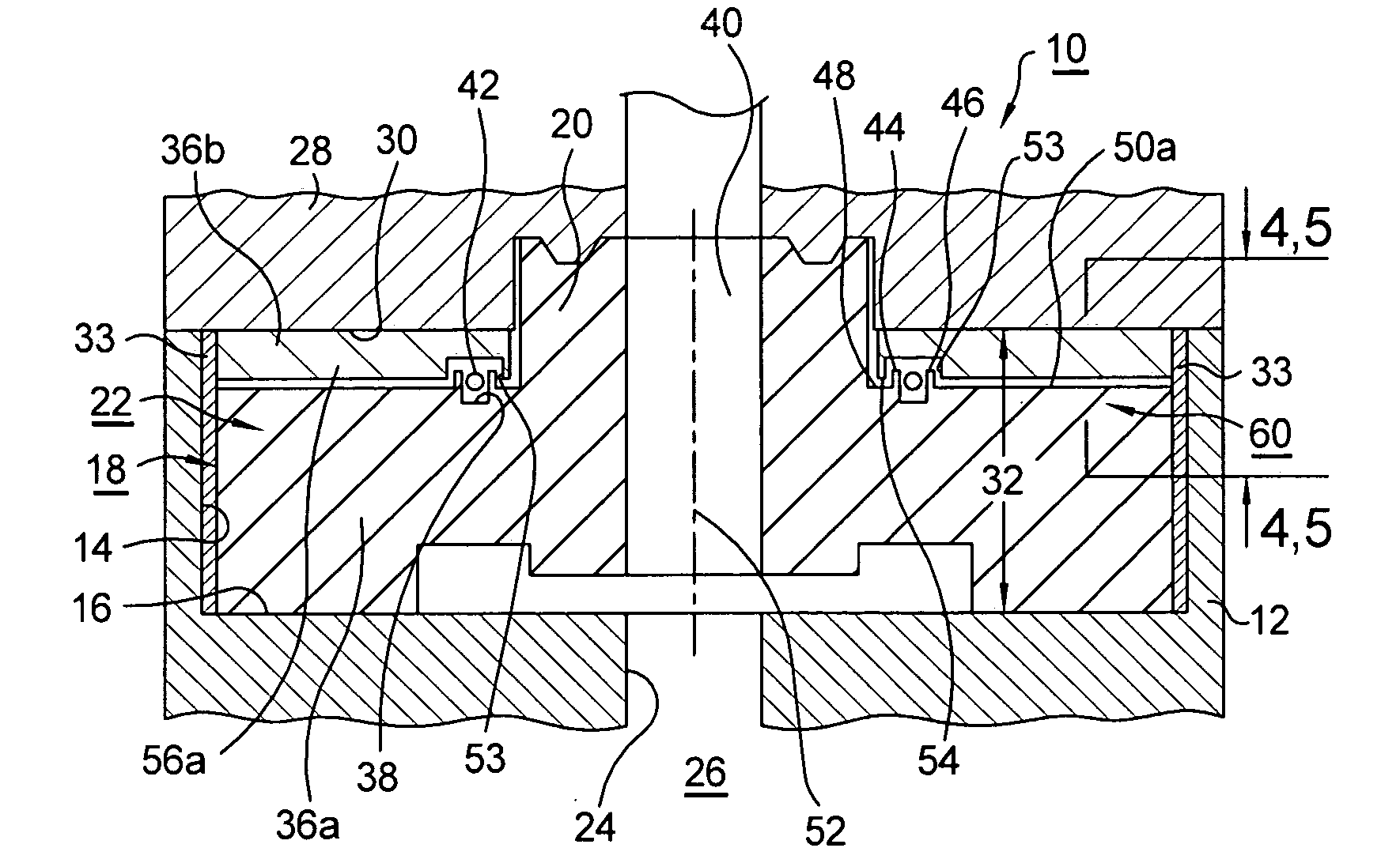
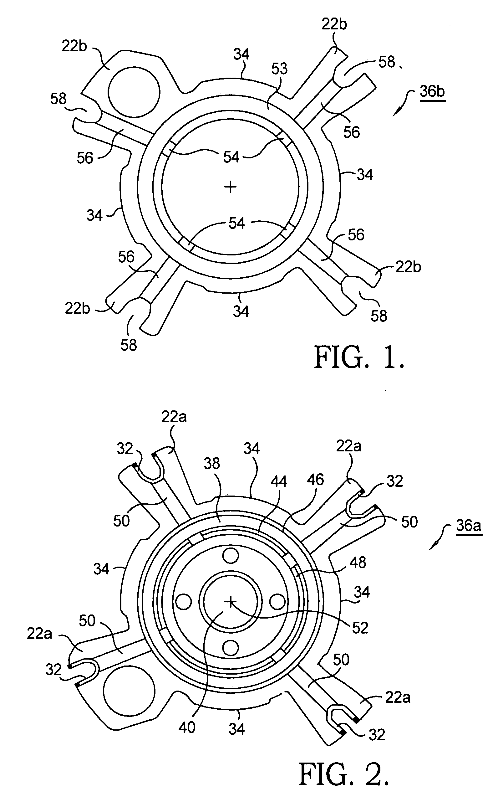
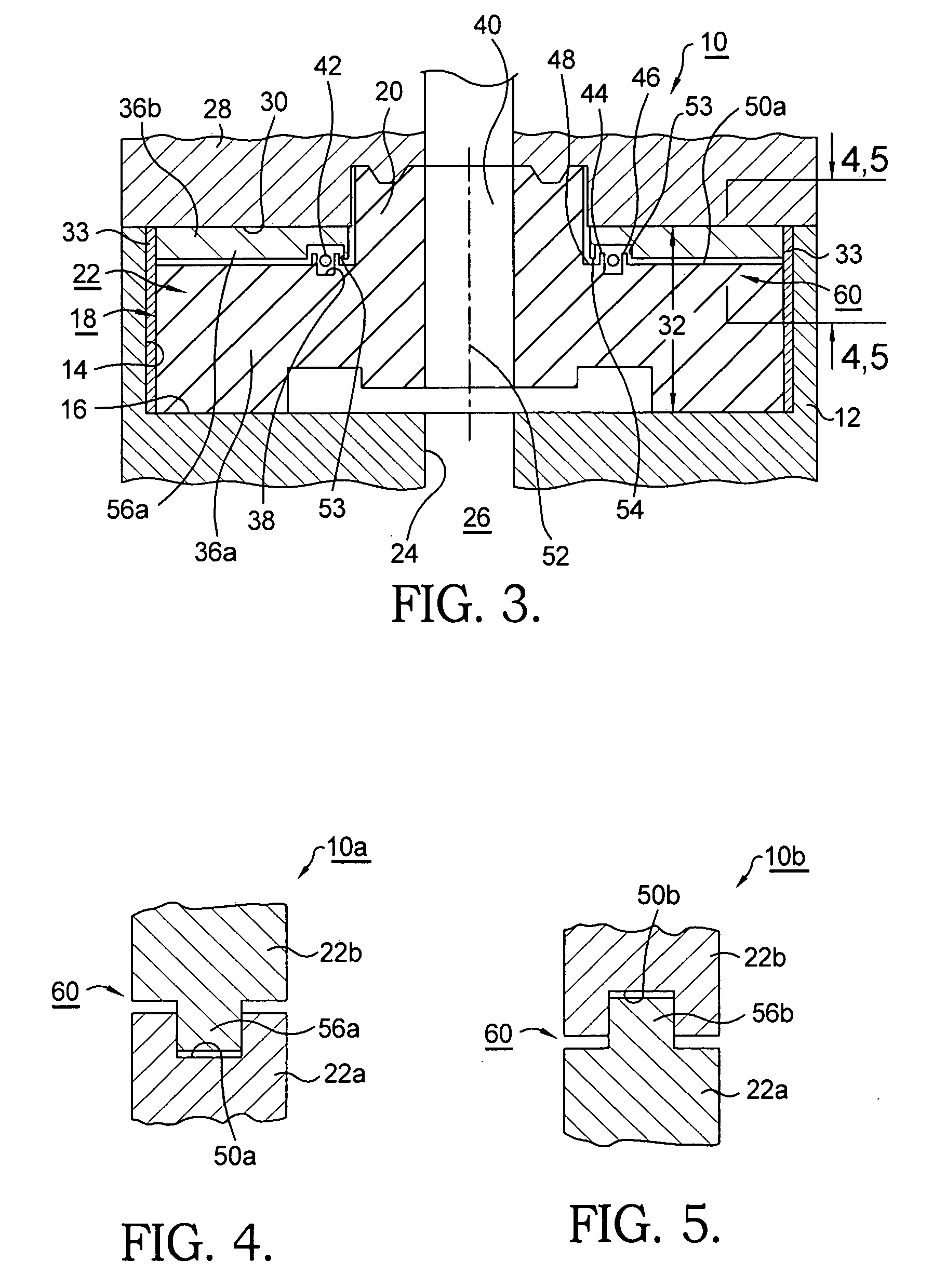
[0016]Referring to FIGS. 1 through 3, an improved vane-type camshaft phaser 10 in accordance with the present invention comprises a pulley or sprocket and stator 12 for engaging a timing chain or belt (not shown) operated by an engine crankshaft (not shown). Stator 12 is provided with radial walls 14 and a stator plate surface 16 for receiving a rotor 18 having a hub 20 and vanes 22. Hub 20 is coaxial with a central bore 24 in stator 12, allowing access of an end of an engine camshaft (not shown) into rotor hub 20 during mounting of phaser 10 onto an internal combustion engine 26 during assembly thereof. Stator 12 is closed by a rotor cover plate 28 having a surface 30 opposite stator plate surface 16, forming advance and retard chambers between the rotor and the stator and defining a first height 32. Seals 33 are mounted at the ends of vanes 22 for sweeping radial walls 14 to prevent oil leakage past vanes 22 during operation of phaser 10. Similar seals (not shown) may be mounted i...


PUM


Abstract

A camshaft phaser for varying the timing of valves in an internal combustion engine. A rotor includes a plurality of vanes disposed in a stator having a plurality of lobes, forming a plurality of alternating timing advance and timing retard chambers. Pressurized oil is supplied selectively to the chambers to change the phase angle of the camshaft with respect to the crankshaft. The rotor is captured between a stator plate and a rotor cover plate. Axial surfaces of the rotor form wiping surfaces with their respective plates. The rotor is divided equatorially into two interlocking sections, the lower section riding on the stator plate and the upper section riding on the cover plate. An axially slidable labyrintian seal formed at the juncture of the upper and lower sections prevents oil leakage. A lash spring between the upper and lower sections urges the sections into zero-lash with their respective plates.

Description

RELATIONSHIP TO OTHER APPLICATIONS AND PATENTS[0001]The present application is a Continuation-In-Part of a pending U.S. patent application, Ser. No. 11 / 638,595, filed Dec. 13, 2006.TECHNICAL FIELD[0002]The present invention relates to vane-type camshaft phasers for varying the phase relationship between crankshafts and camshafts in internal combustion engines; and more particularly, to a phaser wherein the rotor is formed in two slidably interlocking sections with a compression spring disposed therebetween such that the two sections are urged in opposite directions against the stator plate and the rotor cover plate, respectively, to control oil leakage past both plates; the two rotor sections are sealed against leakage therebetween by an axially slidable labyrinthian seal.BACKGROUND OF THE INVENTION[0003]Camshaft phasers for varying the phase relationship between the crankshaft and a camshaft of an internal combustion engine are well known. A prior art vane-type phaser generally com...

Claims


Application Information

Patent Timeline
Patent Type & Authority Applications(United States)
IPC IPC(8): F16D3/10
CPCF01L1/022F01L1/3442F01L2001/34479F01L2101/00F16D3/10F16D3/84F01L2301/00
Inventor URCKFITZ, JASON M.
Owner DELPHI TECH INC
Why Eureka
Try Eureka