Fluid Dynamic Pressure Bearing

a dynamic pressure bearing and bearing technology, applied in the direction of sliding contact bearings, mechanical energy handling, mechanical equipment, etc., can solve the problems of reducing the effect of the diameter of the inner circumference of the sleeve on the accuracy of the sleeve, the dimensional accuracy and the assembling accuracy are harder to ensure, and the sleeve is easy to construct, and the sleeve is easy to maintain. , the effect of high quality

Inactive Publication Date: 2009-06-25
MINEBEA CO LTD
View PDF8 Cites 17 Cited by
  • Summary
  • Abstract
  • Description
  • Claims
  • Application Information

AI Technical Summary

Benefits of technology

[0015]The present invention solves the problems of the conventional fluid dynamic pressure bearings and maintains dimensional and geometric accuracy of the sleeve when it is fitted in the case. The present invention also ensures that the case and sleeve are reliably adhered together with the adhesive, and at the same time offers a fluid dynamic pressure bearing that is high in quality, easy to construct and is suitable for low-cost manufacturing, and is able to maintain long-term airtightness, thereby preventing the leakage of lubricant fluid.
[0016]Moreover, the present invention provides a recording disk drive device having a spindle motor that can maintain a high degree of reliability and wherein the contamination by the adhesive agent used to bond the fluid dynamic pressure bearing cases and sleeves is prevented. The present invention also provides a spindle motor that can be used in other applications such as an axial flow fan and wherein the contamination by the adhesive agent used to bond the fluid dynamic pressure bearing cases and sleeves is prevented.
[0017]In the present invention, after the case is fitted to the sleeve during the assembling of the fluid dynamic pressure bearing, the adhesive is injected into the adhesive groove of the sleeve, from the exterior circumference surface of the case through the opening formed in the case. With this adhesive, the inner circumference surface of the case and the outer circumference surface of the sleeve are adhered together, firm and airtight, and thus the gap between the two parts is completely sealed by the adhesive, the lubricant is prevented from leaking from the gap, and thereby the lubricant that is added to the inside of the fluid dynamic pressure bearing is completely retained in the inside. Also, unlike in the case of the conventional method of fitting by coating with an adhesive the fitted surface previously to the fitting of the sleeve and the case, problems such as the inadequate adherence of the sleeve and the case due to adhesion failure when the adhesive is partially carried outward during the fitting and is spread unevenly on the fitting surface, and the contamination of parts that arises when the outwardly carried adhesive adheres to parts other than the fitting surface do not occur. Also, because problems that occur during the assembly process, such as the handling, are mitigated, manufacturing efficiency is increased, making mass production of the fluid dynamic pressure bearing possible.

Problems solved by technology

However, as further miniaturization occurs, it becomes harder to secure the dimensional accuracy and assembling accuracy of the parts that constitute the fluid dynamic pressure bearings, and it is getting harder to mass-produce the product at low costs.
Through this, the length where the pressure arises at the time of press fitting is kept short and so reduces the effect on the accuracy of the size of the diameter of the inner circumference of the sleeve 202.
However with this method the interference between the case 107 and the sleeve 102 must be large and so the dimensional accuracy becomes distorted by the high pressure force and the galling of the fitted surfaces, therefore, with this method, it is difficult to maintain high accuracy of the inner circumference of the said sleeve 102, and, at the same time, to maintain airtightness at the fitted surfaces of sleeve 102 and case 107.
Even if the method of fitting the parts by previously coating the fitted surface with an adhesive is adopted to keep the sleeve 102 and case 107 firmly adhered together, the applied adhesive is not evenly coated on the fitted surface because part of adhesive is taken outward during fitting, and the adhesion failure will make it impossible for sleeve 102 and case 107 to be firmly adhered together or the outwardly taken adhesive will adhere to parts other than the fitted surface, thereby generating a contamination problem in that area.
Additionally, there are problems regarding reducing the number of process steps, and processing time, thus posing obstacles to low-cost mass production.
Also, unlike in the case of the conventional method of fitting by coating with an adhesive the fitted surface previously to the fitting of the sleeve and the case, problems such as the inadequate adherence of the sleeve and the case due to adhesion failure when the adhesive is partially carried outward during the fitting and is spread unevenly on the fitting surface, and the contamination of parts that arises when the outwardly carried adhesive adheres to parts other than the fitting surface do not occur.

Method used


Image

  • Fluid Dynamic Pressure Bearing
  • Fluid Dynamic Pressure Bearing
  • Fluid Dynamic Pressure Bearing

Examples


Embodiment Construction

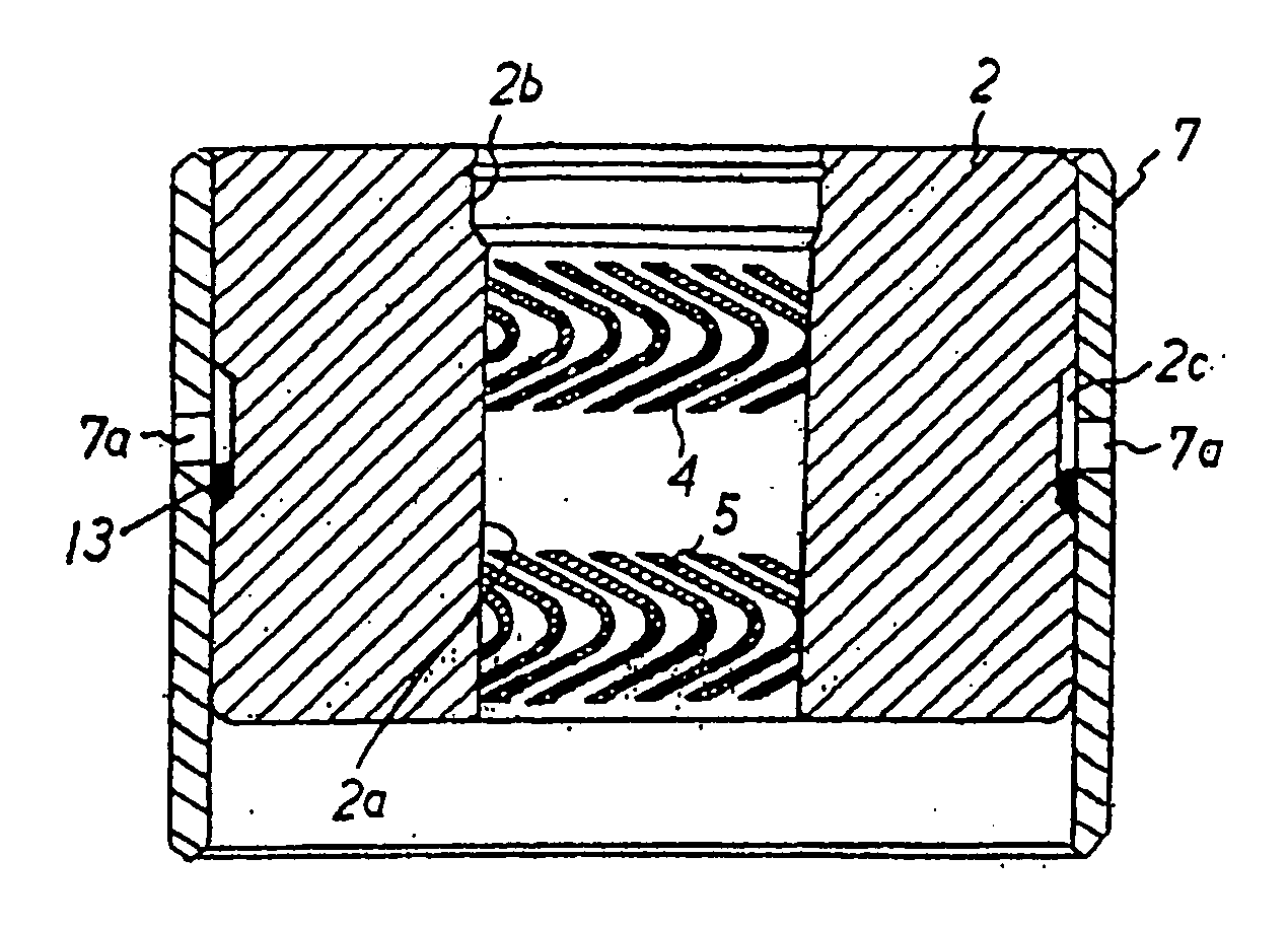
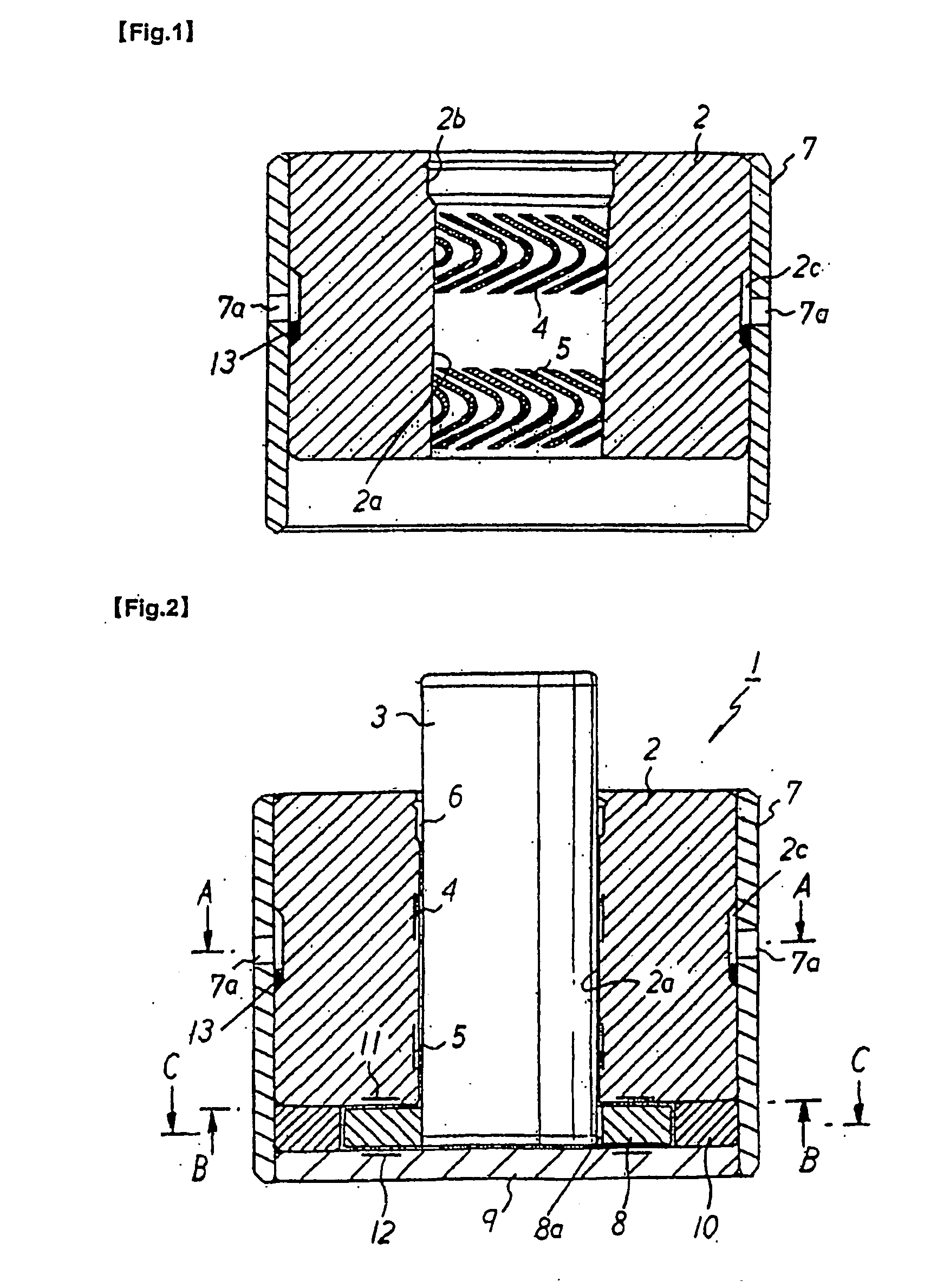
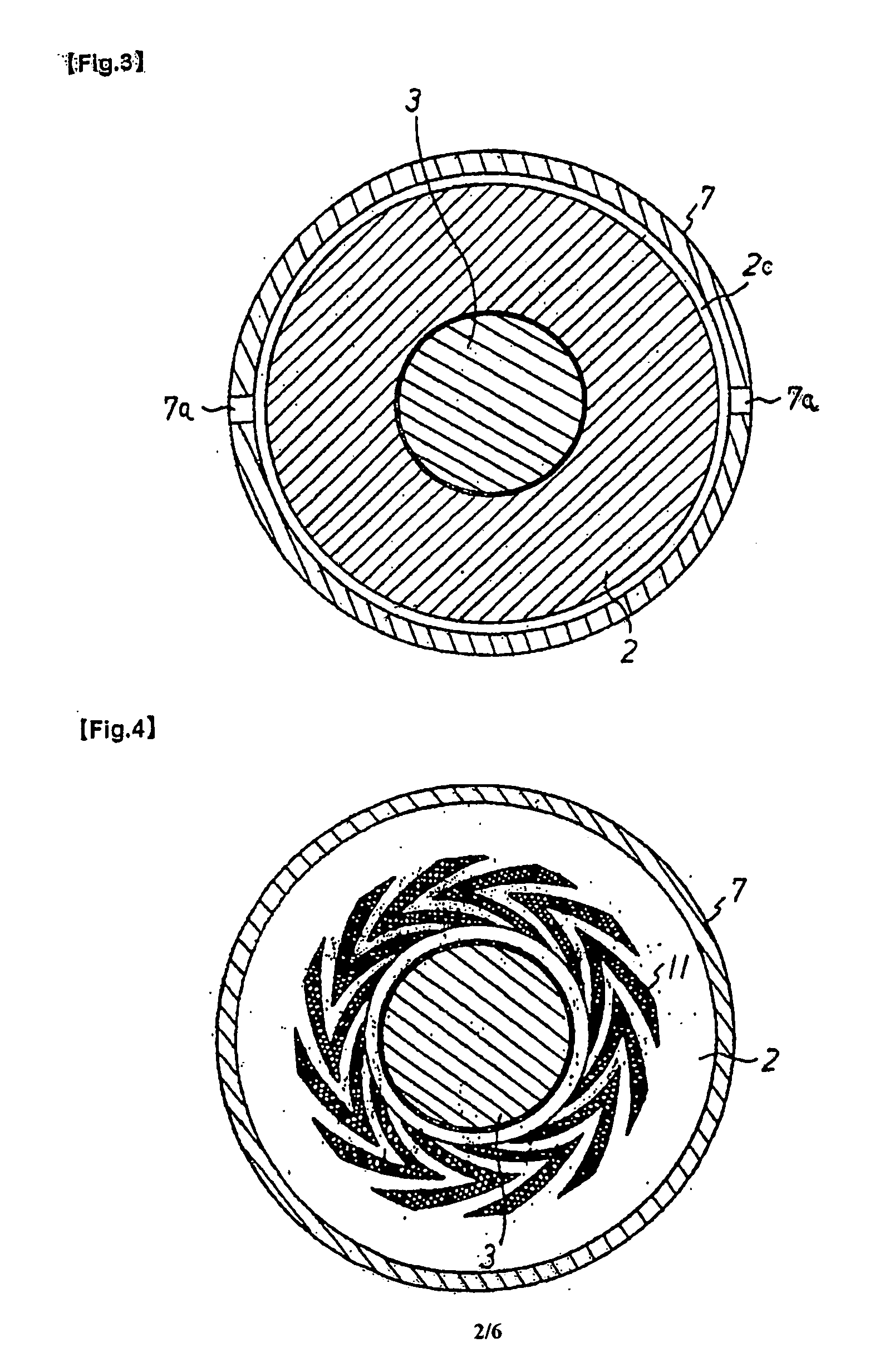
[0032]FIG. 2 shows a fluid dynamic bearing 1 having a cylindrical sleeve 2. A rotating shaft 3 (for example, in this embodiment, a spindle of the spindle motor) is inserted into a round hole 2a of the sleeve 2, and a minute radial gap with a ring-shaped plan view section is formed between the inner circumferential surface of round hole 2a and the outer circumferential surface of rotating shaft 3. As presented in FIG. 1, on top and bottom sections separated in the axial direction (i.e., upward and downward direction) of the inner circumferential surface of round hole 2a of sleeve 2, dynamic pressure generating herringbone-shaped grooves 4 and 5 are formed around the entire circumference. In the upper edge of the inner circumferential surface of the round hole 2a an expanded diameter section 2b, is provided (see FIG. 1) which forms a lubricant reservoir 6 having a ring-shaped plan view section with the outer circumferential surface of the rotating shaft 3 (see FIG. 2).

[0033]Also, in t...


PUM


Abstract

A fluid dynamic bearing (1) with a rotating shaft (3) inserted into a sleeve (2) fitted into a case (7) is disclosed. Tree rotating shaft (3) rotates freely without contact with the sleeve (2) by means of dynamic pressure force generated by the lubricant fluid that fills the gap formed around the rotating shaft (3). An adhesive groove (2c) is formed around the entire outer circumferential surface of the sleeve (2). At least one hole (7a) facing the adhesive groove (2c) is formed in case (7), and case (7) and sleeve (2) are; adhered by the injection of an adhesive (13) into adhesive groove (2c) from the hole (7a). The fluid dynamic pressure bearing, manufactured in this manner provides a high-quality bearing that is easy to construct, that can be adapted to low-cost manufacturing, and that can maintain dimensional and structural accuracy and in which the case (7) and sleeve (2) can be reliably adhered together with the adhesive (13). Such bearing will maintain long-term airtightness of the joint between the sleeve (2) and the case (7) and prevent leakage of lubricant fluid during manufacture. The bearing can be used for a spindle and other compact motors for driving memory devices for magnetic discs and optical discs (such as a CD or a DVD), motors for polygon mirrors used for scanning processes of laser beam printers, and for small motors for use such as in axial flow fans.

Description

[0001]This application claims priority based on the following Japanese patent applications: 2004-163607, filed Jun. 1, 2004; and 2005-138649, filed May 11, 2005.BACKGROUND OF THE INVENTION[0002]1. Field of the Invention[0003]This invention relates to fluid dynamic pressure bearings for a spindle and other compact motors for driving memory devices for magnetic discs and optical discs (such as a CD or a DVD), driving motors for polygon mirrors used for scanning processes of laser beam printers, and for small driving motors for use such as in axial flow fans.[0004]2. Description of the Related Art[0005]In recent years, in regards to memory devices for magnetic and optical discs used in computer hardware, the demand for smaller, thinner, and lighter products with high density memory capacity has become strong, and market pressure to lower costs has also increased. Because of this, there is a large demand to increase speed and rotational accuracy and lower costs for spindle motors used t...

Claims


Application Information

Patent Timeline
Patent Type & Authority Applications(United States)
IPC IPC(8): H02K7/08F16C32/06F16C17/10F16C33/08F16C33/10
CPCF16C17/026F16C33/107F16C33/08F16C17/107F16C2370/12
Inventor OBARA, RIKURO
Owner MINEBEA CO LTD
Why Eureka
Try Eureka