Method and apparatus for rapid prototyping of monolithic microwave integrated circuits

a monolithic microwave integrated circuit and rapid prototyping technology, applied in the direction of electrical devices, additive manufacturing apparatus, coupling devices, etc., can solve the problem that the satisfaction of prototyping purposes is not necessarily desirable, and achieve the effect of reducing costs

Inactive Publication Date: 2005-11-17
BAE SYST INFORMATION & ELECTRONICS SYST INTERGRATION INC
View PDF12 Cites 1 Cited by
  • Summary
  • Abstract
  • Description
  • Claims
  • Application Information

AI Technical Summary

Benefits of technology

[0012] In one embodiment, when utilizing gold, a nickel coating is first deposited followed by the sputtering of the gold, with the gold surfaces provided with a microfine finish so that circuit losses are minimized and so as to preserve dimensional accuracy. Moreover, rather than soldering the active elements to the housing as was done in the past, conductive adhesive is utilized for electrically connecting and mounting the active elements to the sputtered conductive layer.
[0013] The housing itself is made of a material which has a temperature coefficient of expansion such that upon heating in the metallizing process the originally designed dimensions as well as edges and corners are maintained. The plastic in one embodiment is of a high temperature material such that the sputtering temperatures utilized in the sputtering process do not result in bubbling of the metallized coating when, for instance, metal flash techniques are utilized to provide the housing with the appropriate layer. In one embodiment, the layer is less than or 1 / 10,000th of an inch in thickness which while satisfactory for prototyping purposes is not necessarily desirable if the active components are to be soldered to the housing. Moreover, in the subject process the active components are mounted with conductive adhesive such as a silver epoxy, thus eliminating the requirement for the application of heat.
[0015] The result is a non-metallic structure which is much lighter than the brassboard prototyping utilized in the past, with the smoothness of the finish for the housing walls and the metallization reducing losses associated with the propagation structure of the wave energy altered by dimensional and surface factors.
[0018] It is thus possible with the stereolithographic rendering and coating techniques to prepare a suitable prototype in a matter of days as opposed to a matter of weeks and to be able to physically try out an idea and validate that it works in a very short period of time and at lower cost.

Problems solved by technology

In one embodiment, the layer is less than or 1 / 10,000th of an inch in thickness which while satisfactory for prototyping purposes is not necessarily desirable if the active components are to be soldered to the housing.

Method used


Image

  • Method and apparatus for rapid prototyping of monolithic microwave integrated circuits
  • Method and apparatus for rapid prototyping of monolithic microwave integrated circuits
  • Method and apparatus for rapid prototyping of monolithic microwave integrated circuits

Examples


Embodiment Construction

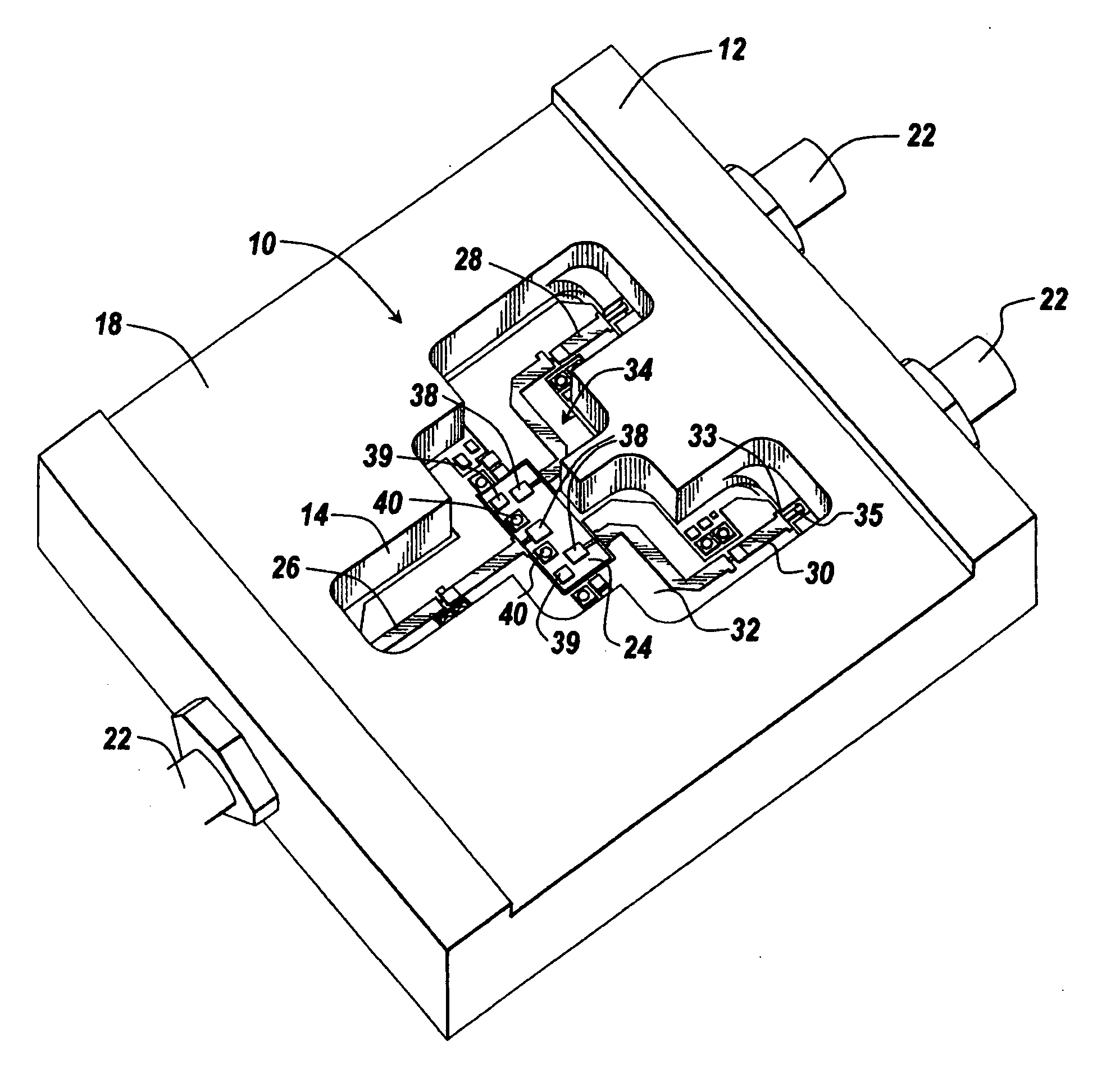
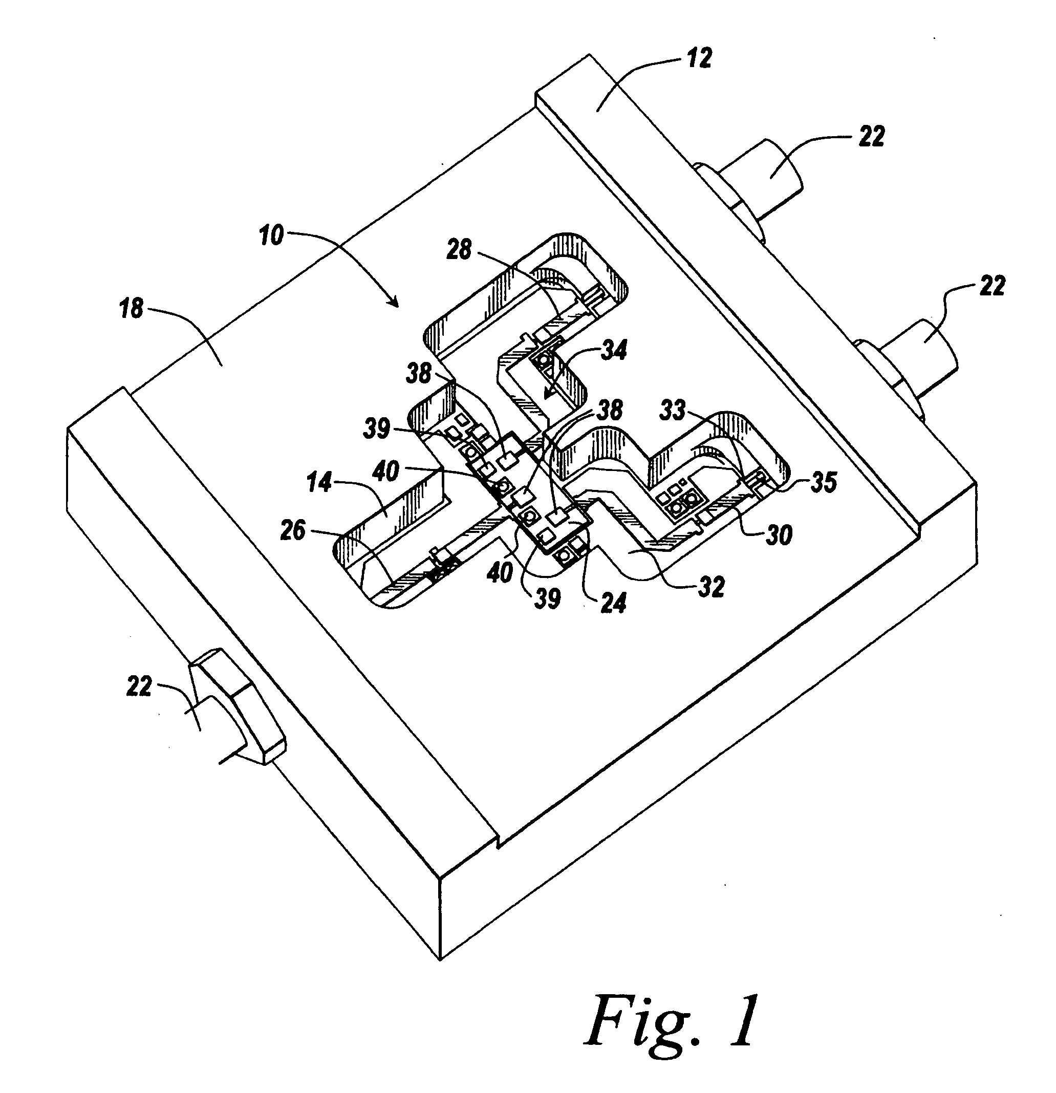
[0025] Prior to discussing the housing and the criticality of the dimensions, it will be appreciated that microwave integrated circuits have components such as conductors, inductors, capacitors, resistors and active circuits which must be positioned relative to the housing with tolerances in the range of thousandths of an inch. What this means is that when one seeks to design a housing into which the components are to fit, there are some critical dimensions which become operative due to the microwave frequencies.

[0026] Rather than simply locating components on a circuit board in an indiscriminate fashion, one needs to pay attention to various dimensions because the wavelengths are so short. If the placement of a part or positioning of a line or trace is inconsistent with good design practice, the performance of the circuit can be degraded or can even be unacceptable.

[0027] For instance, misplacement of the components may cause detuning and may cause undesirable reflections, becaus...


PUM

PropertyMeasurementUnit
thicknessaaaaaaaaaa
Raaaaaaaaaaa
smoothnessaaaaaaaaaa

Abstract

A system is provided for rapidly prototyping monolithic microwave integrated circuit modules to provide an experimental structure that can be physically made to operate by stereolithographically rendering an SLA part directly from the designer's drawings and by coating the part with a conductive layer, with the smoothness being better than 0.001 inch and with the dimensional accuracy being better than 3 mils for some applications. In one embodiment, the coating for the SLA model is made from either rhodium or gold having a thickness of less than 1 / 10,000th of an inch, with a nickel barrier being first deposited followed by the gold. The particular SLA plastic is a high temperature plastic to prevent bubbling during the metal deposition step which in one embodiment involves sputtering. The coated model has a microfinish of Ra<0.001 inch, with active devices being electrically attached to the coating through the use of conductive adhesives or eutectic solder. This provides a device in which active devices are attached to the layer without soldering and without introduction of heat which might destroy the metallized layer and alter and the critical dimensions.

Description

RELATED APPLICATIONS [0001] This Application is a continuation of pending U.S. patent application Ser. No. 10 / 787,577 filed Feb. 26, 2004, the contents of which are incorporated herein by reference.FIELD OF INVENTION [0002] This invention relates to rapid prototyping of microwave modules and more particularly to the utilization of metal coating of a stereolithographic assembly (SLA) model for the provision of a physical model that can function as an active microwave electronic circuit suitable for testing and demonstration. BACKGROUND OF THE INVENTION [0003] Microwave and monolithic microwave modules have been formed in which the circuits themselves are mounted into a passive electrically conductive housing or carrier and have active electronic elements such as filters, mixers, switches, amplifiers, and the like epoxied or soldered to the interior of the housing, with a top lid hermetically sealing the housing. The devices are made of plates or sheets of conductive material such as ...

Claims


Application Information

Patent Timeline
Patent Type & Authority Applications(United States)
IPC IPC(8): B29C35/04H01P1/10H01P1/15H01P1/20
CPCH01P1/15B33Y80/00
Inventor PERKINS, THOMAS O.UURTAMO, STEPHEN J.
Owner BAE SYST INFORMATION & ELECTRONICS SYST INTERGRATION INC
Why Eureka
Try Eureka