Eureka AIR delivers breakthrough ideas for toughest innovation challenges, trusted by R&D personnel around the world.

Hydrodynamic bearing unit

Inactive Publication Date: 2005-01-18
NTN CORP +1
View PDF5 Cites 16 Cited by
  • Summary
  • Abstract
  • Description
  • Claims
  • Application Information

AI Technical Summary

Benefits of technology

It is therefore an object of the present invention to provide a structure of a bearing unit capable of preventing oil leakage by securely preventing the touch between accumulated oil and a sealing member within a housing.
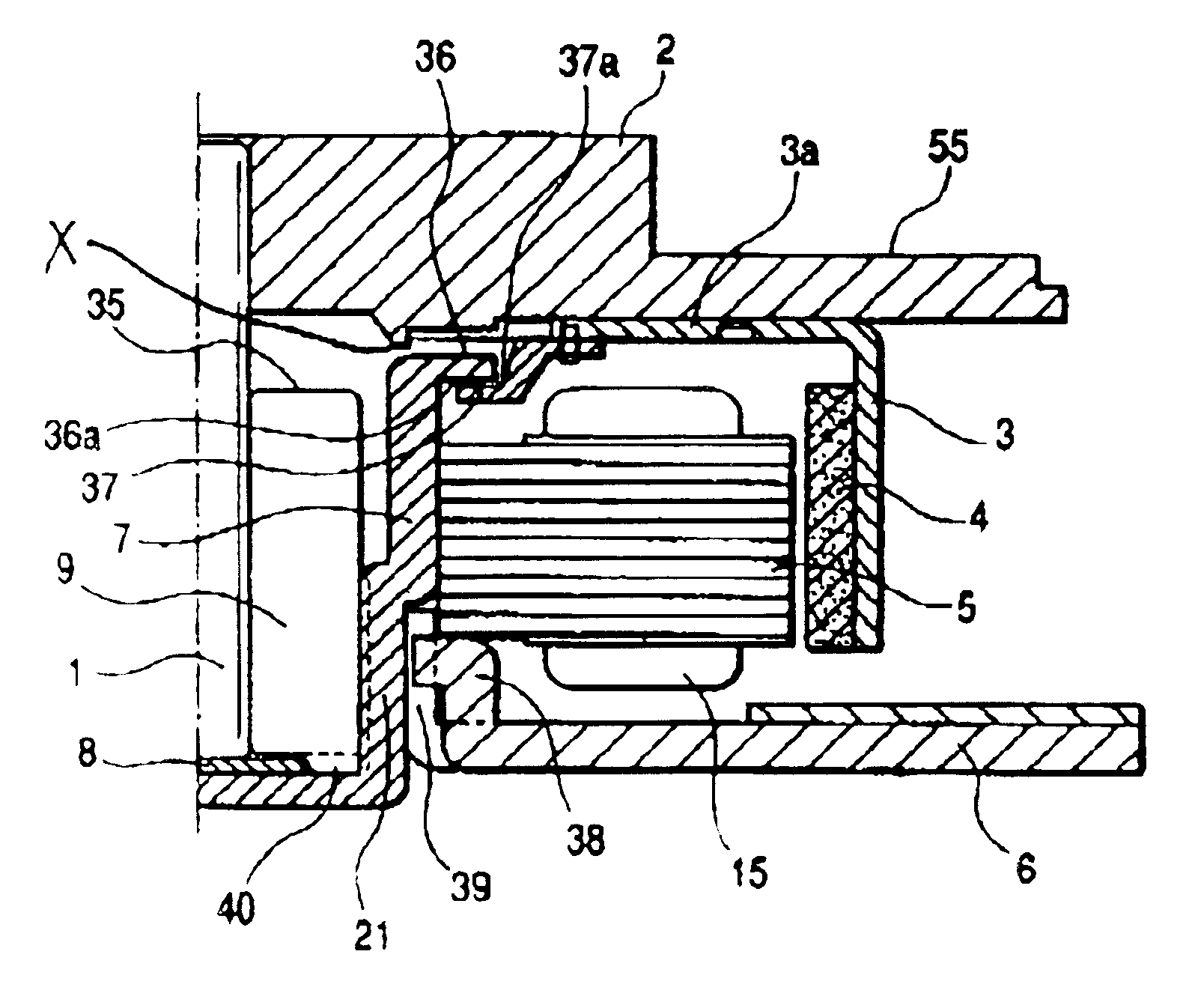
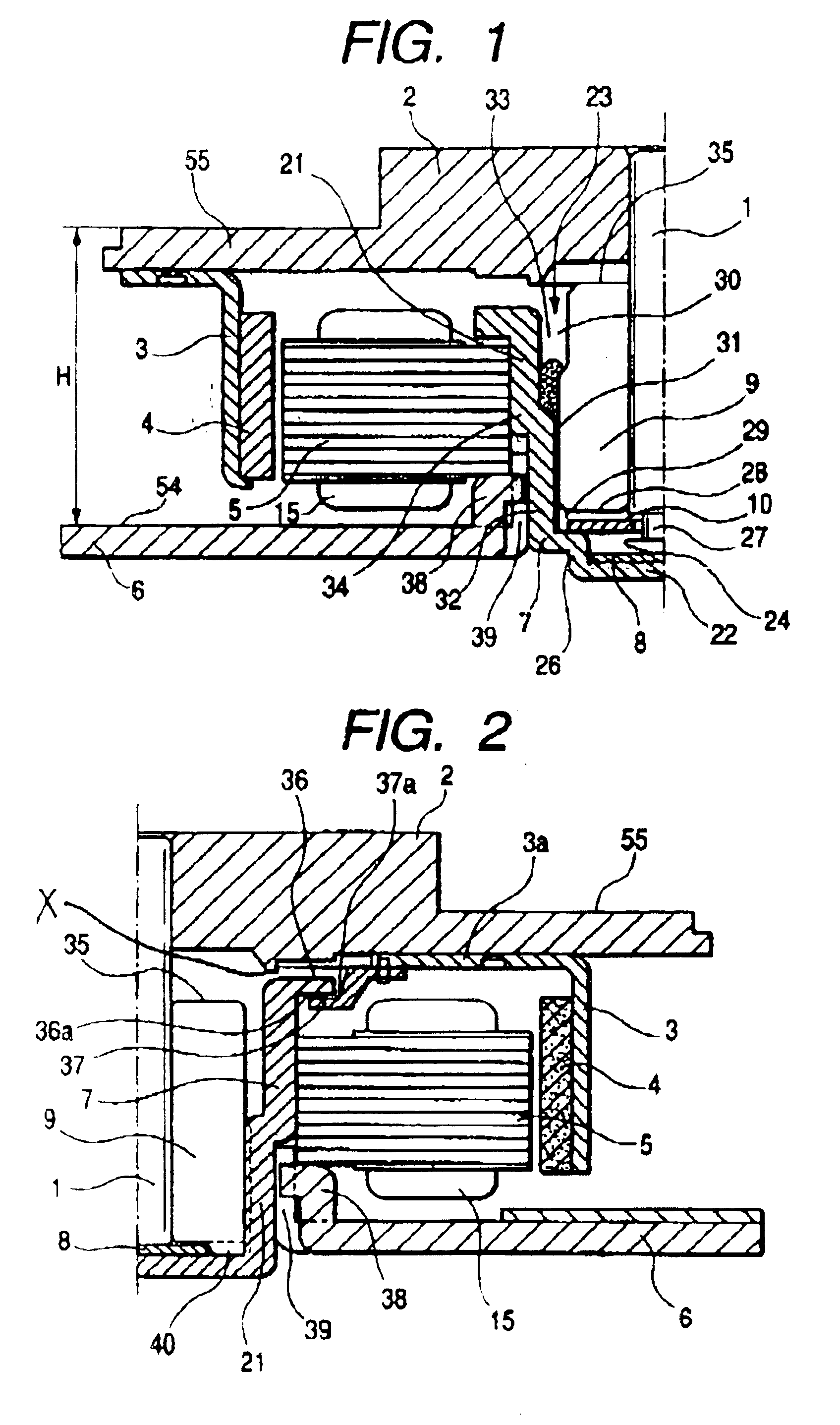
Provision of the oil reservoir makes it possible to accumulate the oil pushed upwardly into the opening side of the housing via the ventilation path or oozing from the bearing member during bearing operation therein. The oil reservoir is formed at the end portion of the opening side of the housing between the inner periphery of the housing and the outer periphery of the bearing member, in other words, is formed in the area extending from the end surface of the bearing member on the opening side of the housing toward the anti-opening side of the housing. Therefore, the surface level of the accumulated oil in the oil reservoir can be lowered toward the anti-opening side of the housing to a larger extent than that of the accumulated oil seen in the conventional bearing unit. Consequently, the distance between the sealing member and the accumulated oil surface is elongated and therefore, the touch between the sealing member and the accumulated oil surface caused by the bubble expansion, the tilted physical orientation of motor during operation or the amount variation of oil to be filled can be prevented.
In this case, the volume of the oil reservoir is preferably designed to be larger than the volume increase of the oil during bearing operation. This makes it possible to lower the surface level of the accumulated oil in the oil reservoir from the end surface of the bearing member on the opening side of the housing toward the anti-opening side of the housing.
The ventilation path can be concretely configured to include a first path formed between the inner periphery of the housing and the outer periphery of the bearing member, and a second path formed between an end surface of the bearing member on the anti-opening side of the housing and a surface of the housing facing the end surface. With such configuration, when inserting the spindle into the bearing member in an assembling process, the air trapped in the space enclosed by the spindle, the bearing member and the housing is released to open air via the second path and the first path in order, whereby the insertion of spindle can be carried out easily. In this case, it is desirable that the first path of the ventilation path is made so as to communicate with the oil reservoir.
The bearing unit may be configured so that a gap is formed between an end surface of the bearing member on the opening side of the housing and the sealing member in an axial direction. This makes the distance between the accumulated oil surface in the oil reservoir and the sealing member further elongated, thereby effectively preventing the touch between the accumulated oil surface and the sealing member.
The above-described hydrodynamic bearing unit can be configured to have a thrust bearing section in the housing for supporting the spindle in a thrust direction. This makes it possible to stably support the spindle even when the unit is applied to the apparatus employing the structure that thrust load is imparted to a spindle.

Problems solved by technology

In addition, such phenomenon as the amount variation of oil to be filled possibly becomes a primary cause of the above-mentioned touch.

Method used


Image

  • Hydrodynamic bearing unit
  • Hydrodynamic bearing unit
  • Hydrodynamic bearing unit

Examples


Embodiment Construction

Preferred embodiments of the present invention will be described with reference to FIGS. 1 to 5 below.

FIG. 1 illustrates a cross sectional view of a polygon scanner motor included in a kind of information-processing equipment, a laser beam printer (LBP). The motor comprises a bearing unit U having a bearing member 2 for rotatably supporting a spindle 1 positioned in a vertical orientation, a polygon mirror P mounted near a distal end of the spindle 1, a motor section M mainly composed of a stator ms and a rotor mR facing to each other with a gap formed therebetween in an axial direction. The bearing member 2 is fixed to the inner periphery of a housing 3 mounted to a base 4. Reference numerals 6 and 7 denote a rotor hub and a pre-load spring for pressing a polygon mirror P to the rotor hub 6, respectively. When the stator mS is energized, the rotor mR rotates in response to the excitation force generated between the stator ms and the rotor mR mounted to the rotor hub 6, and in accor...


PUM


Abstract

A hydrodynamic bearing unit is provided, by which the touch between oil and a sealing member in a housing is prevented to prevent oil leakage. A bearing member made of a sintered lubricant-containing metal is disposed along the inner periphery of the housing and a spindle is supported in a non-contact manner by the hydrodynamic oil pressure that is generated in a bearing gap by the rotation of the spindle. The opening of the housing is sealed by the sealing member. A ventilation path is formed so as to communicate a sealed space enclosed by the distal end of the spindle at the bottom of the housing, the bearing member and the housing with open air. An oil reservoir is formed between the inner periphery of the housing and the outer periphery of the bearing member at the end portion of the opening side of the housing. The oil reservoir is made so as to communicate with the ventilation path.

Description

BACKGROUND OF THE INVENTION1. Field of the InventionThe present invention relates to a hydrodynamic bearing unit having superiority in high-precision rotation, high-speed stability, long durability, low noise and the like, and particularly, to a hydrodynamic bearing unit suitable for supporting a spindle of spindle motor used in information-processing equipment. The “spindle motor used in information-processing equipment” used herein includes a spindle motor for driving an optical disk such as CD-R / RWs and DVD-ROM / RAMs, a magneto-optical disk such as MOs, and a magnetic disk such as HDDs, a polygon scanner motor employed in a laser beam printer (LBP) or a copying machine, and the like.2. Description of the Related ArtIn recent years, a hydrodynamic bearing has been attracting much attention as a bearing for supporting a spindle of a spindle motor or a polygon scanner motor employed in the above-mentioned various information-processing equipment. The hydrodynamic bearing supports a s...

Claims


Application Information

Patent Timeline
IPC IPC(8): F16C33/04F16C33/10F16C17/02F16C17/08G11B19/20
CPCF16C17/026F16C33/74F16C33/107F16C17/10F16C17/107F16C25/045F16C33/104F16C33/1085F16C2240/42F16C2370/22
Inventor KOSEKI, KAZUHIKOENDO, MAKOTOKADOWAKI, NORIYUKIMORI, NATSUHIKOKURIMURA, TETSUYA
Owner NTN CORP
Why Eureka
Eureka Blog
Learn More