
System and method for powering a vehicle using radio frequency generators

a radio frequency generator and vehicle technology, applied in the direction of steering control, power supply for propulsion, driver interaction, etc., can solve the problems of increasing the cost of fossil fuels, affecting the ongoing practicality of society to rely largely on fossil fuels, and ozone layer damage,

Active Publication Date: 2008-11-18
REARDEN
View PDF10 Cites 338 Cited by
  • Summary
  • Abstract
  • Description
  • Claims
  • Application Information

AI Technical Summary

Benefits of technology

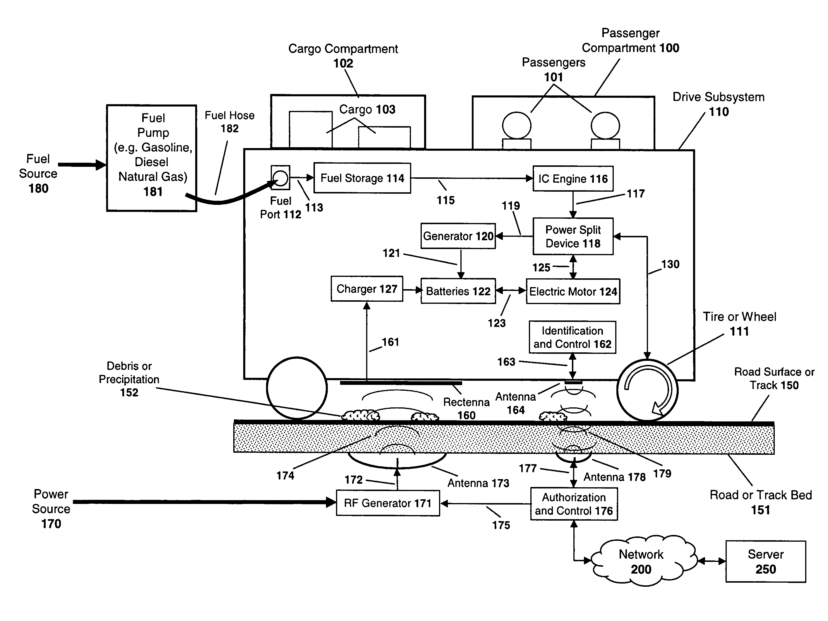
The patent describes a system and method for powering a vehicle using radio signals. The system involves placing RF generators underground to transmit signals to a rectenna on the vehicle, which then uses the signals to generate power. This power is then used to power the vehicle. The technical effect of this system is to provide a new and efficient way to power vehicles using RF signals.

Problems solved by technology

The world's heavy reliance on fossil fuels for vehicular power has resulted in a number of problems and concerns.
IC engine emissions, despite increasingly stringent controls in many countries, contribute significantly to air pollution and release significant quantities of carbon dioxide, potentially harming the ozone layer and / or contributing to global warming.
Many of the world's largest reserves of fossil fuels are in politically unstable areas of the world.
Once the milestone event of peak supply and rapid depletion occurs, the cost of fossil fuel is likely to rise dramatically, further worsening the ongoing practicality for society to rely largely on fossil fuels.
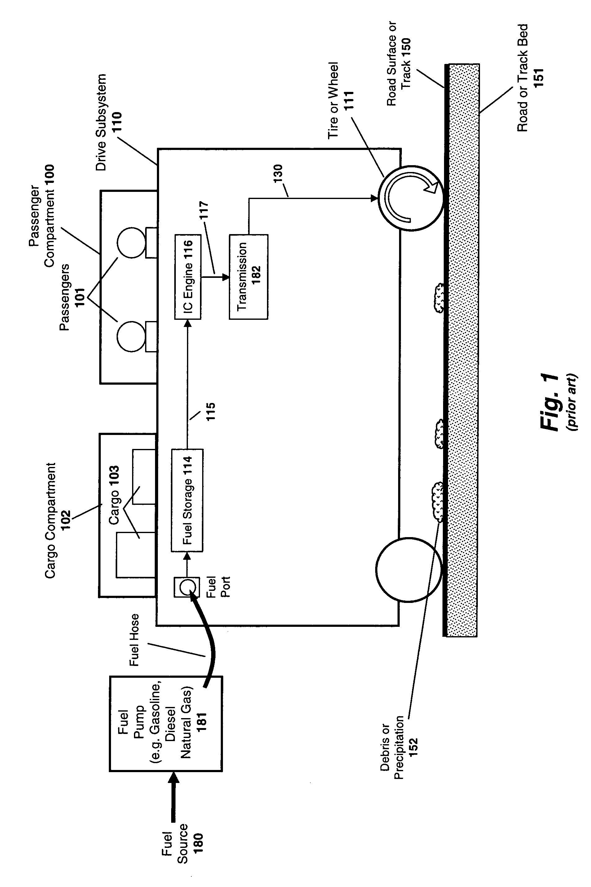
However, with fossil fuel-powered vehicles the energy choices are limited to fossil fuels such as gasoline, diesel, and natural gas that are in liquid or gaseous form and are highly portable.
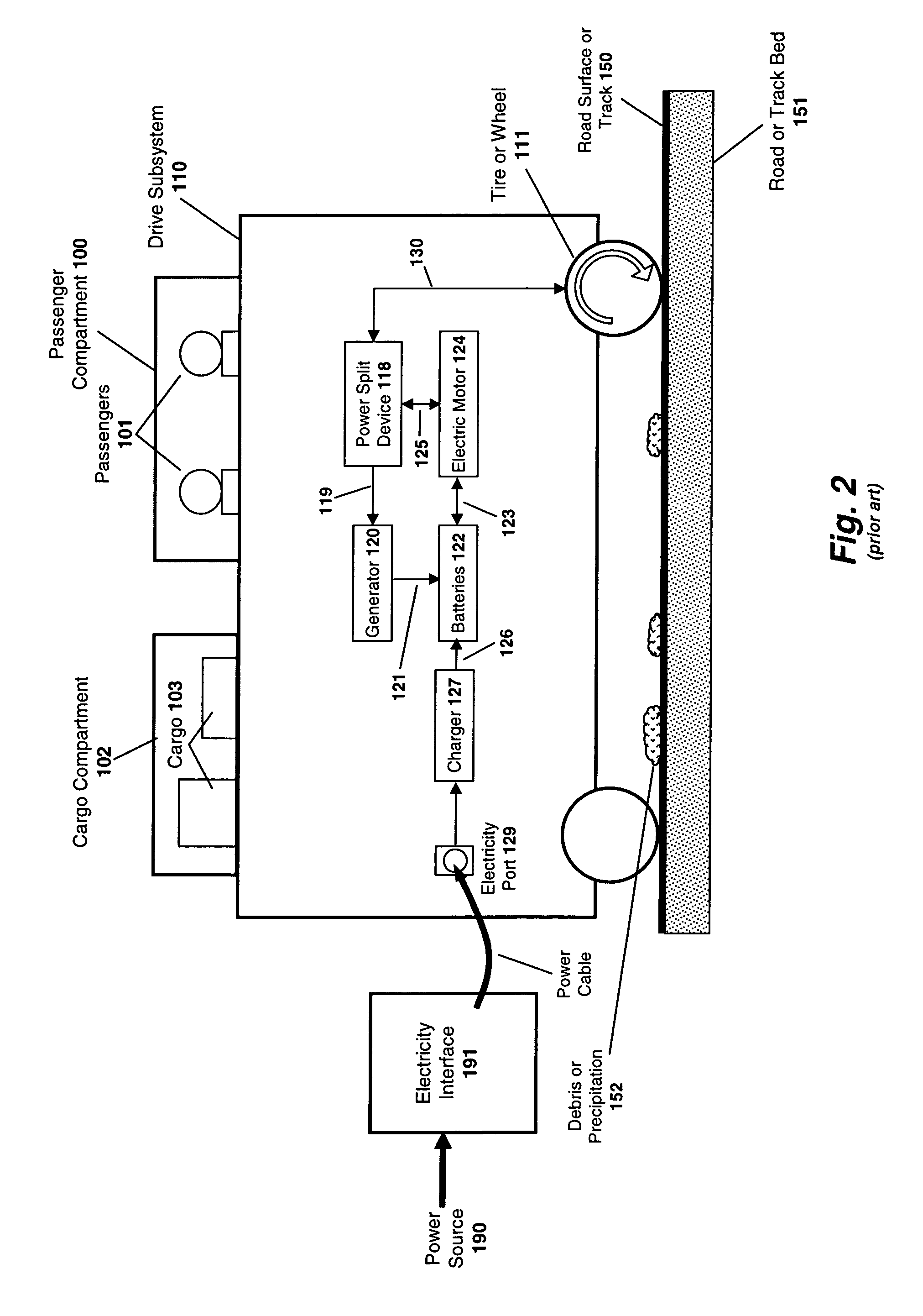
Of course, it is a complex analysis to compare an electric vehicle's overall efficiency to a gasoline vehicle's, but generally speaking, the energy costs for electric vehicles are less expensive per mile compared to similar gasoline vehicles.
Each prior art system developed and / or proposed in the last century to reduce fossil fuel dependence has its advantages and disadvantages, but to date, none has provided a solution which has the convenience and efficiency of a modern IC-powered automobile and offers a long-term solution that eliminates reliance on fossil fuels Several such prior art systems are reviewed here.
One problem with hydrogen vehicles is that hydrogen is not readily available as a fuel source.
Generally, fossil fuels (e.g. natural gas) are used to produce hydrogen, but this defeats the purpose of a non-fossil fueled vehicle.
Although hydrogen may also be produced using electrolysis powered by a electrical source, this process is inefficient and makes hydrogen an unreasonably expensive fuel source.
Independent of electrocution risk, another substantive issue was that cars so connected to the conductive power strips would be quite restricted in their maneuverability, much like toy slot cars, in order to utilize the conductive power source.
In addition, debris or precipitation 152 (e.g. snow, ice, mud, oil, gravel, trash) could obstruct or interfere with the conductive interface.
Because of the precise and close relative spacing requirements (e.g. ±25 mm in one Wampfler AG system) for inductive primaries and secondaries, inductive power transmission is difficult to apply generally to vehicles which may have to operate in a hostile outdoor environment.
His Tesla Coil, which demonstrates the principle of RF power transmission, has been a common fixture in science museums and science classes for decades, but it has found little practical application because it is quite inefficient as a wireless power transmitter.

Method used


Image

  • System and method for powering a vehicle using radio frequency generators
  • System and method for powering a vehicle using radio frequency generators
  • System and method for powering a vehicle using radio frequency generators

Examples


Embodiment Construction

[0056]Described below is an improved apparatus and method for powering a vehicle. In the following description, for the purposes of explanation, numerous specific details are set forth in order to provide a thorough understanding of the present invention. It will be apparent, however, to one skilled in the art that the present invention may be practiced without some of these specific details. In other instances, well-known structures and devices are shown in block diagram form to avoid obscuring the underlying principles of the invention.

[0057]One embodiment of the invention powers a vehicle using wireless radio frequency signals transmitted from an antenna embedded within a roadway to a rectenna on the vehicle. The rectenna may be positioned on the underbody of the vehicle and may be configured to receive the RF signals as the vehicle passes over the transmitting antenna.

[0058]FIG. 9 illustrates one embodiment which includes an RF generator unit 171 positioned beneath the road surf...


PUM


Abstract

A system and method are described for powering a vehicle using radio frequency (“RF”) signals. For example, a method according to one embodiment of the invention comprises: positioning a plurality of RF generators beneath the road surface of a roadway, the RF generators configured to transmit RF signals in the direction of vehicles traveling over the roadway; coupling a rectenna on a vehicle, the rectenna configured to receive the RF signals transmitted from the RF generators and to generate power from the RF signals; and using the power generated by the rectenna to power the vehicle.

Description

BACKGROUND OF THE INVENTION[0001]1. Field of the Invention[0002]This invention relates generally to the field of vehicle propulsion systems. More particularly, the invention relates to an improved system and method for powering a vehicle using radio frequency signals.[0003]2. Description of the Related Art1. Introduction[0004]Developing vehicles which reduce reliance upon fossil fuels is a matter of critical global importance. Fossil fuels (e.g., gasoline, diesel fuel, natural gas) are used in the vast majority of vehicles in the world because of fossil fuels' high energy density, fast refueling time, relatively low cost, and the maturity of internal combustion (“IC”) engines that run on fossil fuels.[0005]The world's heavy reliance on fossil fuels for vehicular power has resulted in a number of problems and concerns. IC engine emissions, despite increasingly stringent controls in many countries, contribute significantly to air pollution and release significant quantities of carbon ...

Claims


Application Information

Patent Timeline
Patent Type & Authority Patents(United States)
IPC IPC(8): B60L9/00B60L50/16
CPCB60L11/123B60L11/14B60L11/182G07F15/005H02J7/025H02J17/00B60L2200/26Y02T10/7005Y02T10/7077Y02T90/12Y02T90/122Y02T90/128Y02T90/14Y02T10/6217Y02T10/7072H02J50/10H02J50/80B60L2250/20Y04S30/14B60L50/61B60L50/16B60L53/12B60L53/65H02J7/00034Y02T90/16Y02T10/62Y02T10/70Y02T90/167H02J50/40B60L5/005H02J50/27B60Y2200/91B60Y2200/92
Inventor PERLMAN, STEPHEN G.
Owner REARDEN
Learn More