Refill case

a refill case and case body technology, applied in the field of refill cases, can solve the problems of limited middle plate to be put in the refill case, inability to restore the sealing state of the middle plate, and the refill case in itself cannot seal the middle plate that has been put therein, so as to reduce the sealing function, reduce the elastic deformation range, and save the cost

Active Publication Date: 2008-11-18
YOSHINO KOGYOSHO CO LTD +1
View PDF14 Cites 36 Cited by
  • Summary
  • Abstract
  • Description
  • Claims
  • Application Information

AI Technical Summary

Benefits of technology

[0033]This invention having the above-described configuration has the following effects:
[0034]In the invention of claim 1, the user can carry a middle plate in the sealed state with no regard to a new or used one. Thus, the user away from home is free to replace the middle plate inside the compact case with any desired middle plate in the refill case. This situation makes it possible for the user to utilize an expensive compact case more effectively.
[0035]The gasket is fitted to the cap under the configuration that the gasket is embraced by the cap in a state having play. Therefore, the gasket is capable of shifting its position relative to the cap. Even if the torsional deformation might occur in the gasket when the cap is screwed on the case body, it would disappear immediately because this shift in position is caused by the elastic nature of the gasket. Thus, the sealing function of the gasket can be performed stably because the gasket is free from any inconvenient deterioration caused by the torsional deformation.
[0036]Furthermore, the butting wall is disposed between the case body and the cap, and prevents the cap from being screwed overly and causing too much gasket deformation that exceeds the range of elastic deformation. Because of this action of the butting wall, the gasket never gets excessive permanent deformation or damage enough to reduce the sealing function.
[0037]In the invention of claim 2, the rubber is capable of performing its high sealing function.
[0038]In the invention of claim 3, it has become reasonably possible that the case body comprises a portion for receiving and retaining the middle plate and the other portion which is brought to screw engagement with the cap. Due to this configuration, the case body can be molded easily. Since the screw cylinder has a foot portion, there can be fewer opportunities for the middle plate to be affected by the impact from outside. Thus, the cosmetic item inside the middle plate can be safely protected.

Problems solved by technology

However, in the case of conventional art disclosed in Patent Document 1, the refill case in itself has no ability to seal the middle plate that has been put therein.
Thus, the problem arises from the fact that the middle plate to be put in the refill case is limited to the one which has been sealed as disclosed in Patent Document 2.
In the conventional art in which Patent Documents 1 and 2 are combined, it becomes impossible to restore the middle plate to the sealed state once the middle plate is opened by peeling off the sealing film.
Therefore, another problem is that after the middle plate has been opened, there is no utility for the refill case of Patent Document 1, thus making such a refill case economically inefficient.
Furthermore, once the middle plate has been opened, it cannot be sealed again unless it is fitted in the compact case.
Therefore, if the user wants to change a cosmetic item to another one, there is no alternative other than finishing up the cosmetic or discarding the one now in use together with the middle plate.
Users have been dissatisfied with quite an inconvenient situation in which they cannot fully utilize the expensive cosmetic remaining in the middle plate.

Method used


Image

  • Refill case
  • Refill case
  • Refill case

Examples


Embodiment Construction

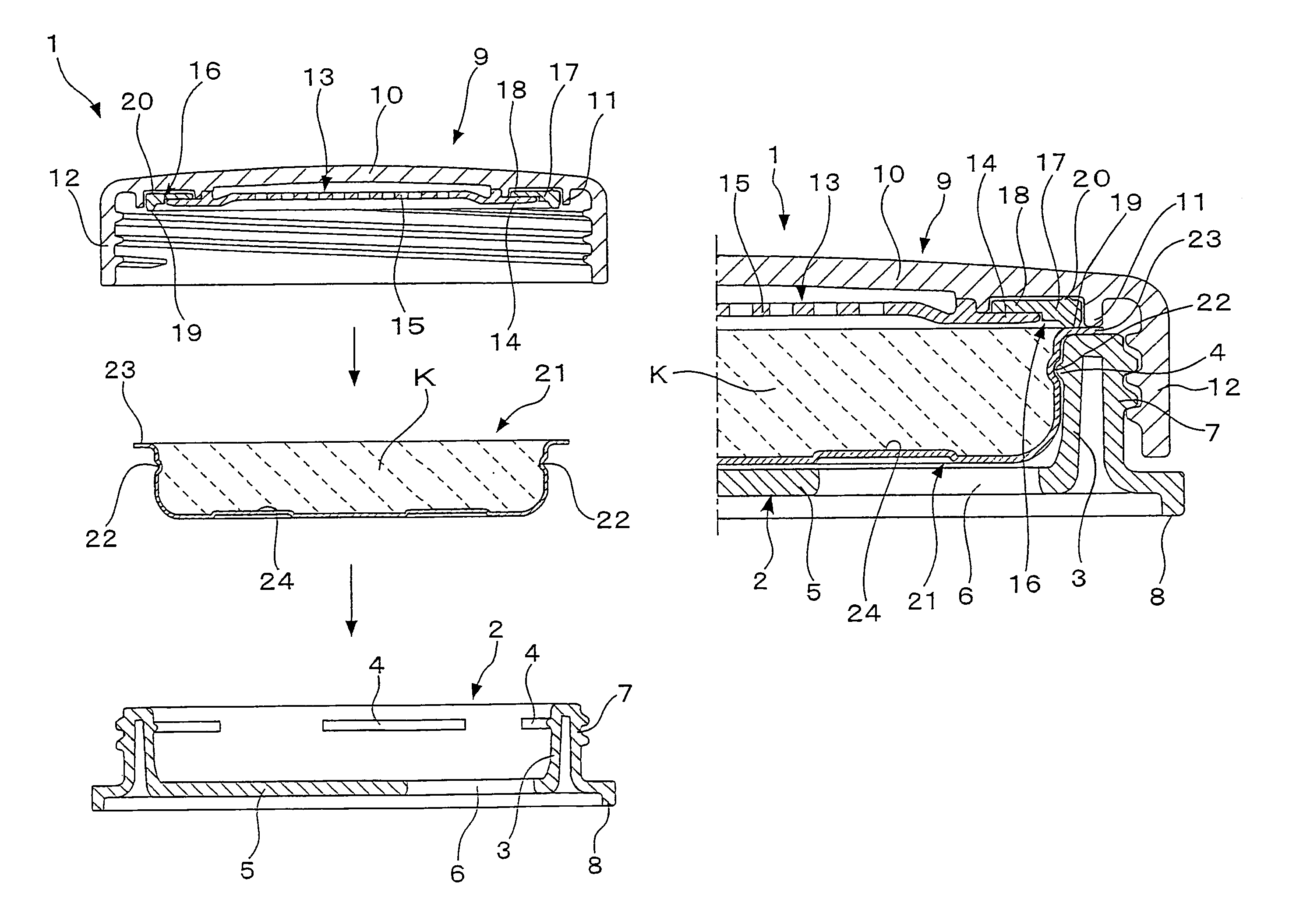
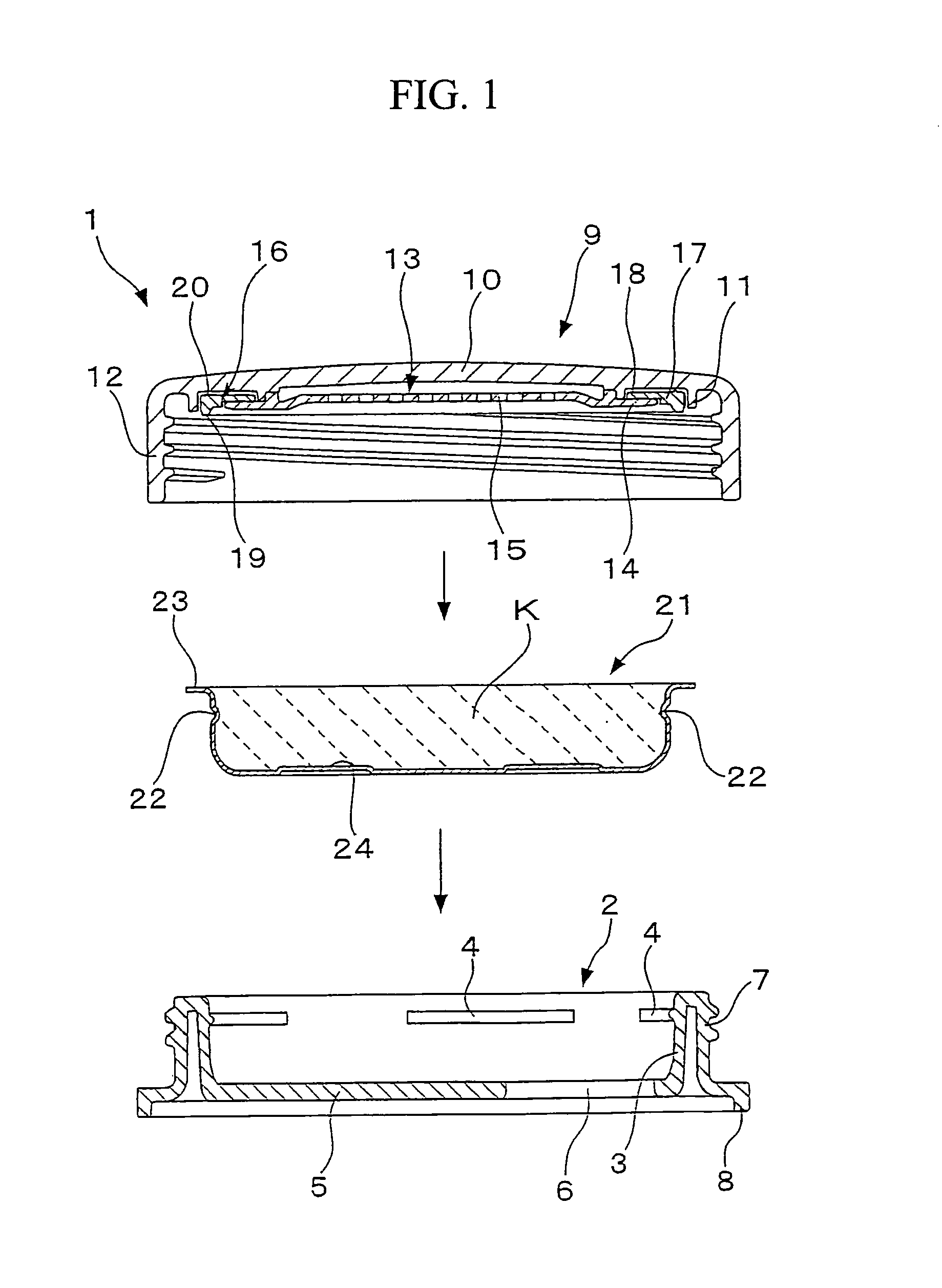
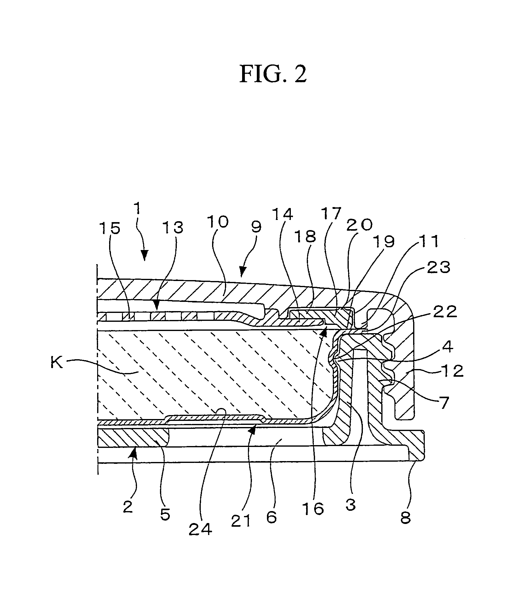
[0046]This invention is further described with respect to preferred embodiments, now referring to the drawings. As shown in FIG. 4, this invention refers to a refill case 1 in which to carry a replaceable middle plate 21 that contains a cosmetic material K. The middle plate 21 made of a metal sheet is tight fit in the refill case 1, and is detachably built into the compact case 25.

[0047]The compact case 25 (See FIG. 4) in which to fit the middle plate 21 comprises a main body 26 in a bottomed cylindrical shape, a lid 29 which is connected by hinges to this main body 26 at respective rear sides so that the lid 29 turns relative to the main body 26 to open or close the compact case 25, and an inner frame 28 which is disposed inside the main body 26 and forms the space accepting and keeping the middle plate 21.

[0048]A poking hole 27 is open in the bottom of the main body 26 of the compact case 25. A rod (not shown) is inserted into the hole to push up the built-in middle plate 21 so th...


PUM

PropertyMeasurementUnit
shapeaaaaaaaaaa
elasticaaaaaaaaaa
elastic deformationaaaaaaaaaa

Abstract

A refill case that includes a middle plate, the middle plate has a bottomed short cylinder shape that contains a cosmetic item and an outward brim along the periphery, a case body that accepts and keeps the middle plate, and a cap that is fitted around the case body detachably in screw engagement. The refill case also includes a ring-shaped gasket made of a soft, elastic material used to seal the middle plate through tight contact of the brim, and a butting wall disposed on either one of the case body or the cap to butt against the other one at a position in which screw engagement of the cap is complete and in which soft contact deformation of the gasket is controlled within a range of elastic deformation. The gasket is fitted to the cap in an undetachable manner but having play relative to the roof.

Description

TECHNICAL FIELD[0001]This invention relates to a refill case in which to put a replaceable middle plate containing a cosmetic material.BACKGROUND ART[0002]Cosmetic materials in the shape of powder or solid are put in middle plates, and each middle plate is then kept stored in a compact case. This middle plate containing a cosmetic item is removable from the compact case. Since compact cases of such a type are highly economical and convenient, these compact cases are in heavy usage.[0003]If the compact cases of the type having a removable middle plate are to be used effectively, it is advantageous to utilize a refill case for exclusive use, in which to keep a replaceable middle plate.[0004]There is a prior-art refill case of this type, wherein the lid and the case body are fitted to each other in a lockable manner and wherein either the lid or the case body is provided with a finger-positioning mark having a dent (See Patent Document 1).[0005]The replaceable middle plate need be seal...

Claims


Application Information

Patent Timeline
Patent Type & Authority Patents(United States)
IPC IPC(8): B65D69/00B65D53/00A45D33/00A45D40/16B65D41/04
CPCA45D33/00A45D40/0068B65D43/0231B65D2543/00092B65D2543/00981B65D2543/00527B65D2543/00537B65D2543/00972B65D2543/00296
Inventor KOGA, TADAYASUKAMIMURA, CHIAKIARAI, TSUGIO
Owner YOSHINO KOGYOSHO CO LTD
Why Eureka
Try Eureka