
Seatbelt retractor having a cushioned sensor actuator

a sensor actuator and seatbelt technology, applied in the direction of belt retractors, vehicle safety belts, vehicle components, etc., can solve the problems of significant noise, and achieve the effect of removing objectionable high frequency nois

Inactive Publication Date: 2008-11-25
KEY SAFETY SYST
View PDF12 Cites 21 Cited by
  • Summary
  • Abstract
  • Description
  • Claims
  • Application Information

AI Technical Summary

Benefits of technology

"The invention is a seatbelt retractor assembly with an inertial sensor that detects changes in vehicle speed. The actuator is modified to add a slight springiness to the contact sensor portion in a manner that removes objectionable high frequency noise. This reduces rattle noises above the cutoff frequency, which is typically kept above 300 Hz. The actuator has a pivotal actuator arm with a surface contacting portion resting on the guide surface of the sensor mass and an open slot above the surface contacting portion. The connecting beam structure has a spring rate sufficient to keep the open slot open during normal sensor vibration. This actuator with a spring like cushioned surface contacting portion dramatically reduces rattle noises above the cutoff frequency."

Problems solved by technology

The inventor has discovered that a significant amount of noise arises from movement of the actuator and components linked to it.

Method used


Image

  • Seatbelt retractor having a cushioned sensor actuator
  • Seatbelt retractor having a cushioned sensor actuator
  • Seatbelt retractor having a cushioned sensor actuator

Examples


first embodiment

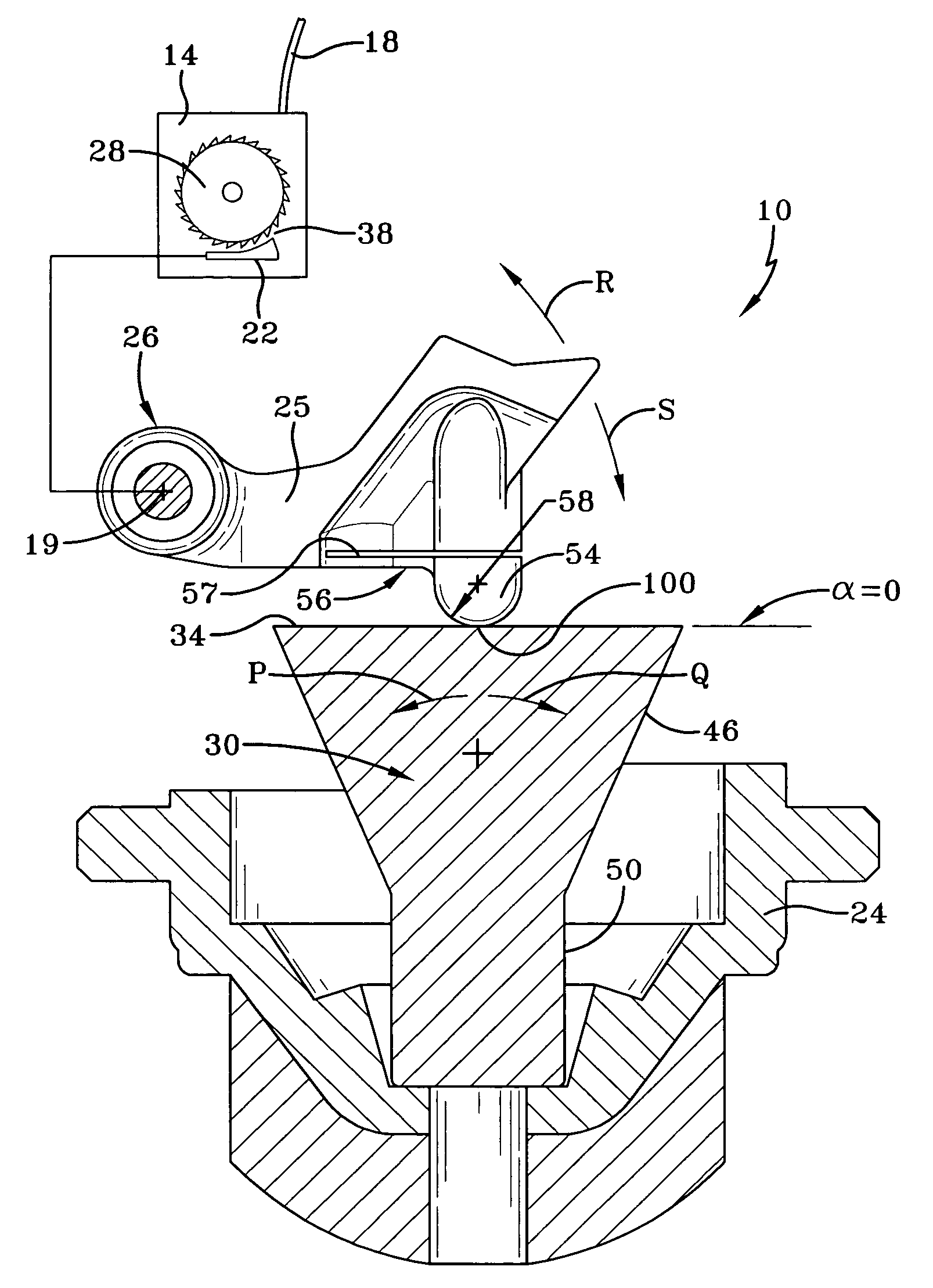
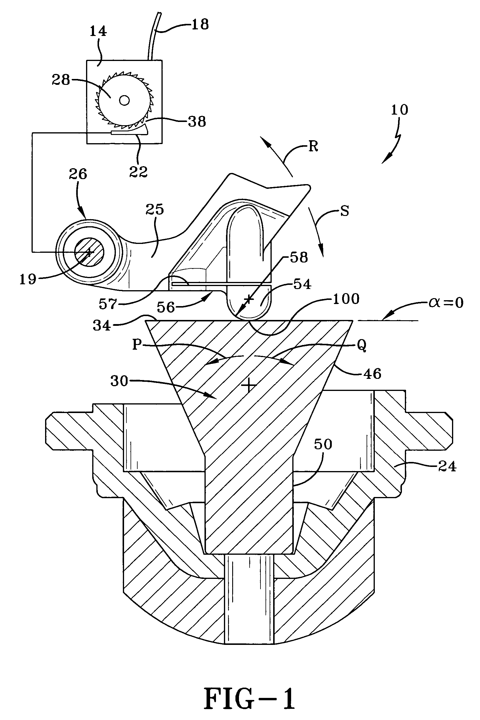
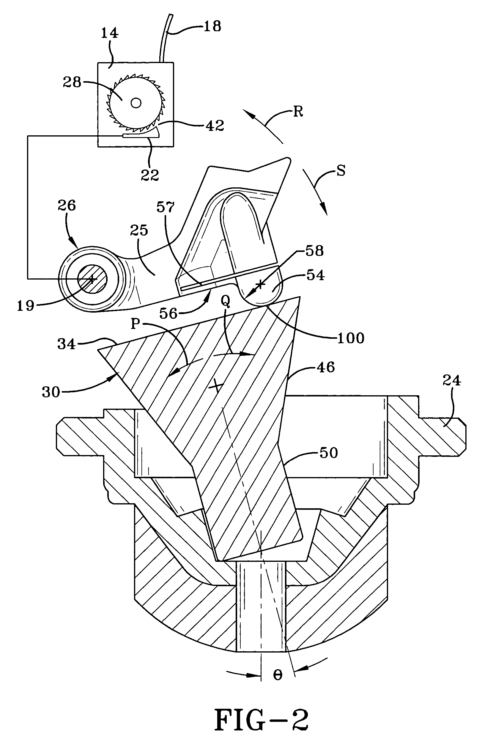
[0025]the invention will now be explained in detail with reference to FIG. 1. As shown in FIG. 1, the guide surface 34 is located on a wide portion 46 above a narrow portion 50. While the figures show a particular shape of an exemplary sensor mass 30 upon which guide surface 34 sits, guide surface 34 may be implemented as any shape such as a sphere or cone shape. Under small amplitude vibration loading, actuator 26 can occasionally “jump” in direction R, momentarily losing contact between guide surface 34 and surface contacting portion 54. When actuator 26 rebounds back in direction S, contact will be re-established. Such intermittent contact can produce an audible rattle noise, which this invention seeks to eliminate. Beam structure 56 reduces the rattle noise by softening the contact between actuator 26 and guide surface 34. If beam structure 56 is made to be softer, the intermittent contact noise becomes quieter. If beam structure 56 is made to be stiffer, the intermittent contac...

second embodiment

[0037]With reference to FIG. 6 the invention is shown wherein the actuator 26 has an open slot 57 that extends substantially vertically with an optional short enlarged end 59 such that the beam structure 56 as shown forms a relatively thin hinge which can reduce the impact noise upon locking into the lock position 42 as well as providing a spring like effect during normal driving conditions.

[0038]Preferably the open slot 57 is at least partially closed in the locked position and the flexibility of the beam structure 56 is sufficient to provide a noise reduction under normal driving condition use as well. As shown the open slot 57, 59 is above the surface contacting portion 54 but offset or located inwardly and extending generally vertically cutting across the width of the actuator arm 25.


PUM


Abstract

A seatbelt retractor assembly (10) has a seatbelt retractor (14) and an actuator (26) for locking and unlocking the seatbelt retractor (1). An inertial sensor mass (30) detects changes in vehicle speed. The mass (30) has a guide surface (34) for interacting with the actuator (26). The guide surface (34) moves between an unlocking position (38) in which the actuator (26) unlocks the seatbelt retractor (14) and a locking position (42) in which the actuator (26) locks the seatbelt retractor (14). The actuator (26) has an actuator arm (25) with a surface contacting portion (54) in contact with the guide surface (34) and an open slot (57) above the surface contacting portion (54). The surface contacting portion (54) is connected to the actuator arm (25) by a beam structure (56) having a spring rate Kbeam sufficient to maintain the open slot (57) open during normal vehicle operation.

Description

FIELD OF THE INVENTION[0001]This invention relates to a seatbelt retractor assembly.BACKGROUND OF THE INVENTION[0002]A seatbelt for a passenger vehicle typically has a seatbelt retractor that serves to retract the belt into its housing. The belt is wound upon a spool in the housing. When the belt is drawn or protracted from its housing, the spool winds a retraction spring, which later retracts the unused portion of the belt onto the spool or withdraws the belt into its housing when not in use.[0003]In the event of a crash, the seatbelt retractor has a lock that prevents the seatbelt from extending further from its housing. The lock may be actuated by an inertial sensor, which responds to changes in vehicle speed during the crash. When a large deceleration is detected, the inertial sensor triggers the lock of the seatbelt retractor to lock the spool and thereby secures the safety belt in place during the crash.[0004]The inertial sensor has an inertial sensor mass that moves in respon...

Claims


Application Information

Patent Timeline
Patent Type & Authority Patents(United States)
IPC IPC(8): B60R22/40
CPCB60R22/40
Inventor MORGAN, CHRISTOPHER D.
Owner KEY SAFETY SYST
Learn More